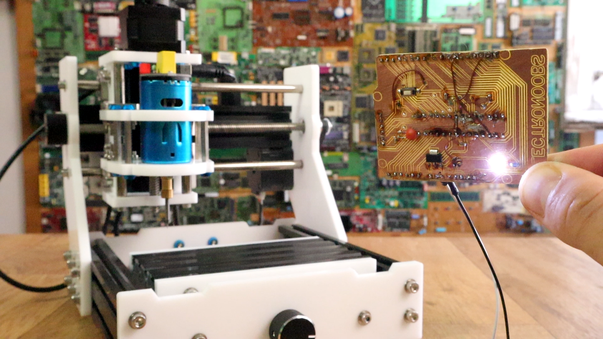
EleksMill CNC engraver
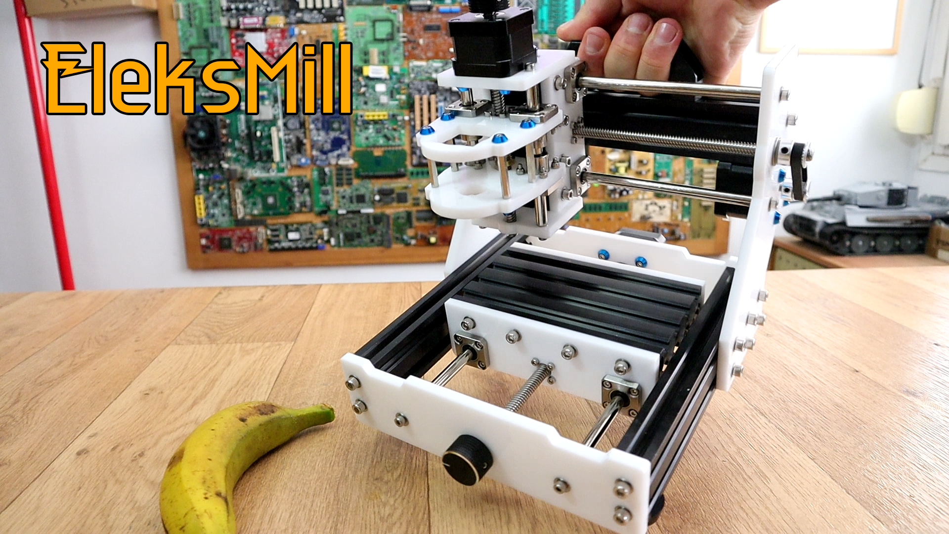
I've just received this machine from banggood. I want to test it and see if I can engrave PCBs with it and create homemade circuits. The frame is very strong with both metal and acrylic parts and it also looks quite good with white and black colors and metalic blue details. It uses 3 step motor to control 3 axis and each has backlash spring. I'm expecting good precision.
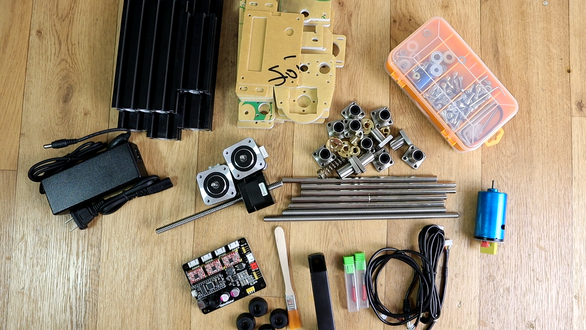
First we haev to mount the machine since it arrives ina a DIY kit. Below we have a photo with all the parts in this kit. There is no guide in the box, but we haev one online with very good details and it will help us mount the machine quite easy. We have the metal bars, the acrylic parts, lead screws, linear bearings, controller board, motors, and a box of screws, washers, etc. We also have the cables, and two 0.1mm drill bits to engrave with. Oh, and also the DC motor as a spindle.
Mounting the frame
Ok so, go
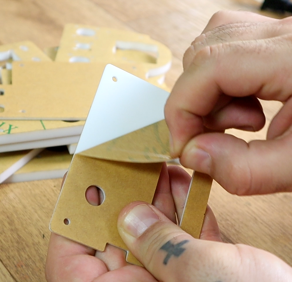
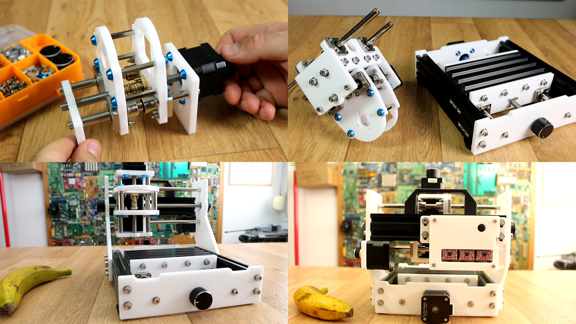
here and follow this guide. It has very well detailed photos. Anyway, we peal each acrylic part and we add the linear bearings and lead screw nuts. We first mount the Z axis part. We add the linear bearings, the lead screw and the Z axis step motor and test if it can move smooth with little friction using the manual rotating knob.
Then, using the metal bars we create the bottom frame. We add the sides and after a few more screws we have the entire frame ready. Mounting it took me around 2 hours and the guide gives me all the steps. That’s it, this below is the final machine.
You have the
full mounting guide ehre.
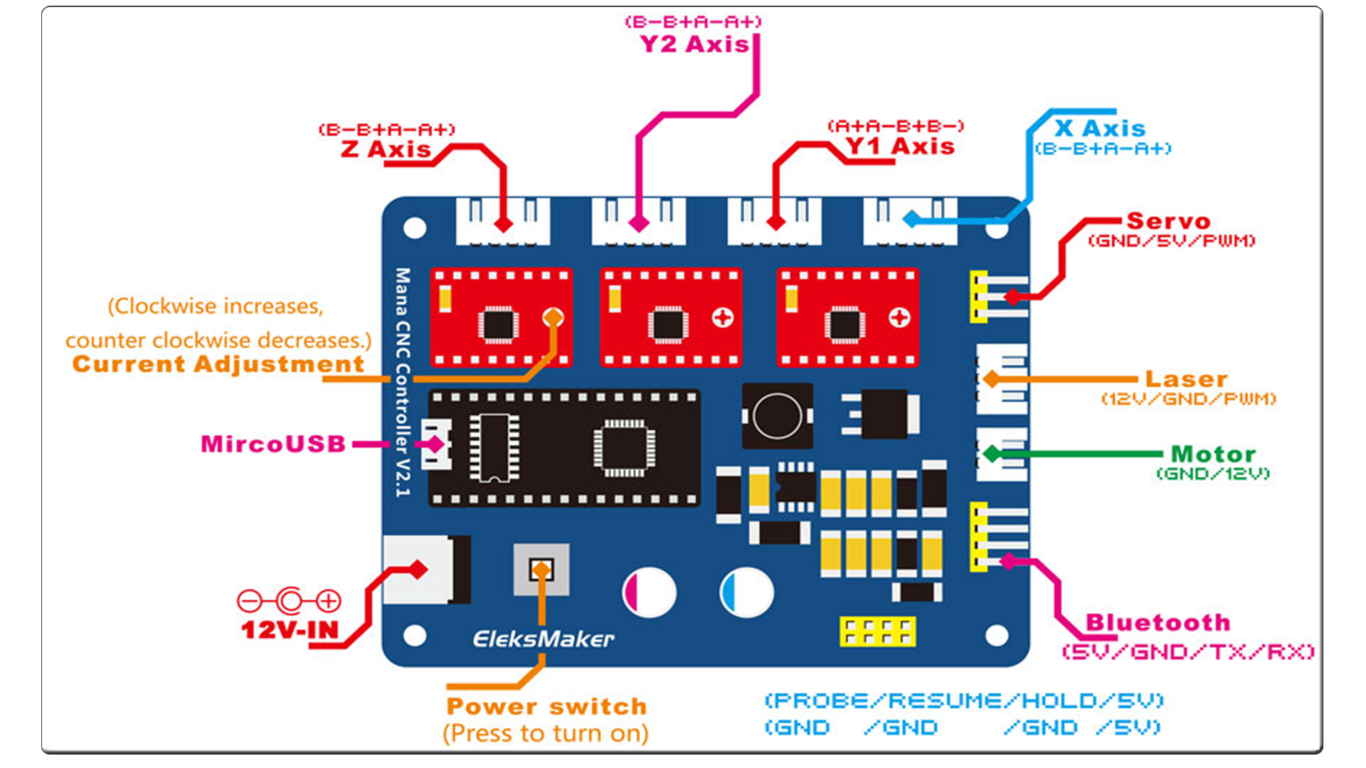
Now taht we haev the frame all we have to do is to place the controller board on the back and the spindle on the Z axis and connect the wires. We have 3 wires for the step motors, one cable for the DC motor, main supply to the board and the USB cable.
Connect everything as in the scheamtic below. As you can see we haev 3 step motors and we could connect both DC motor spindle or a laser module for laser engrave. Now the amchine is ready. Connect the USB to the controller board and to your PC and now let's talk about the software.
bCNC gcode platform
We need to install bCNC. Here is a guide on how to install that platform.
Go to the next link and install bCNC:
LINK bCNC install
It might be in french so transalte the website using Google chrome. You need to isntal Python and Python serial and after that, downlaod the bCNC platform and run it by clicking on bCNC.py file. Now, before we mill the copper board, we need a file to mill.
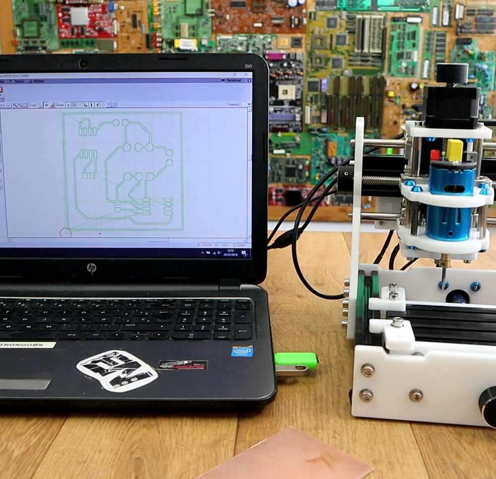
Now we prepare the test file. I've created a simple layout with SMD and DIP components in EasyEDA. Dwonload the gerbers and open FLATCAM.
See how to install FlatCam here:
LINK FLATCAM insatall
Run FLATCAM. Now open the top copper GERBER file. Select it and go to selected. Go to options and make sure you are into mm. Select tool diameter, in my case 0.1 mm and select generate geometry. Now go back to project and select that geometry. Now go to selected and configure the G code. Select the depth, Z travel and feed rate and click generate. Now go back to project, select the G code file and go to selected and click export G code and give it a name. I’ll name mine test file.
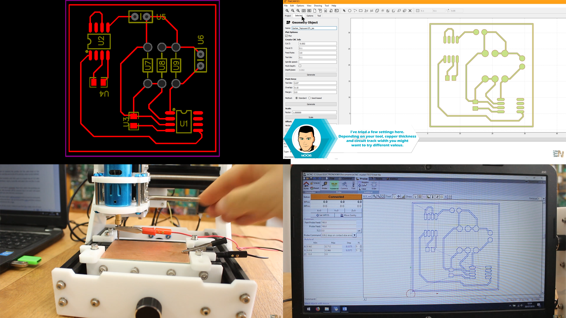
Now prepare the CNC machine. You have to connect the probes for the auto level to the controller board (see scheamtic for pins). Connect the probes here and clip one to the PCB and the other to the drill bit and now we can sense the board error. Now go to BCNC and select the com of the machine and click open at a baud rate of 115 200. Now you could control the CNC in all directions with the controls.
Open a new file and select the test file G code we have created. Now let’s level the board. Go to probe and select autolevel. Now here select margins to define the printing size and then set the interval for the probing process. My first example will be around 3 by 3 cm and I will select 5 intervals for each direction. Select feed rate and click the scan button.
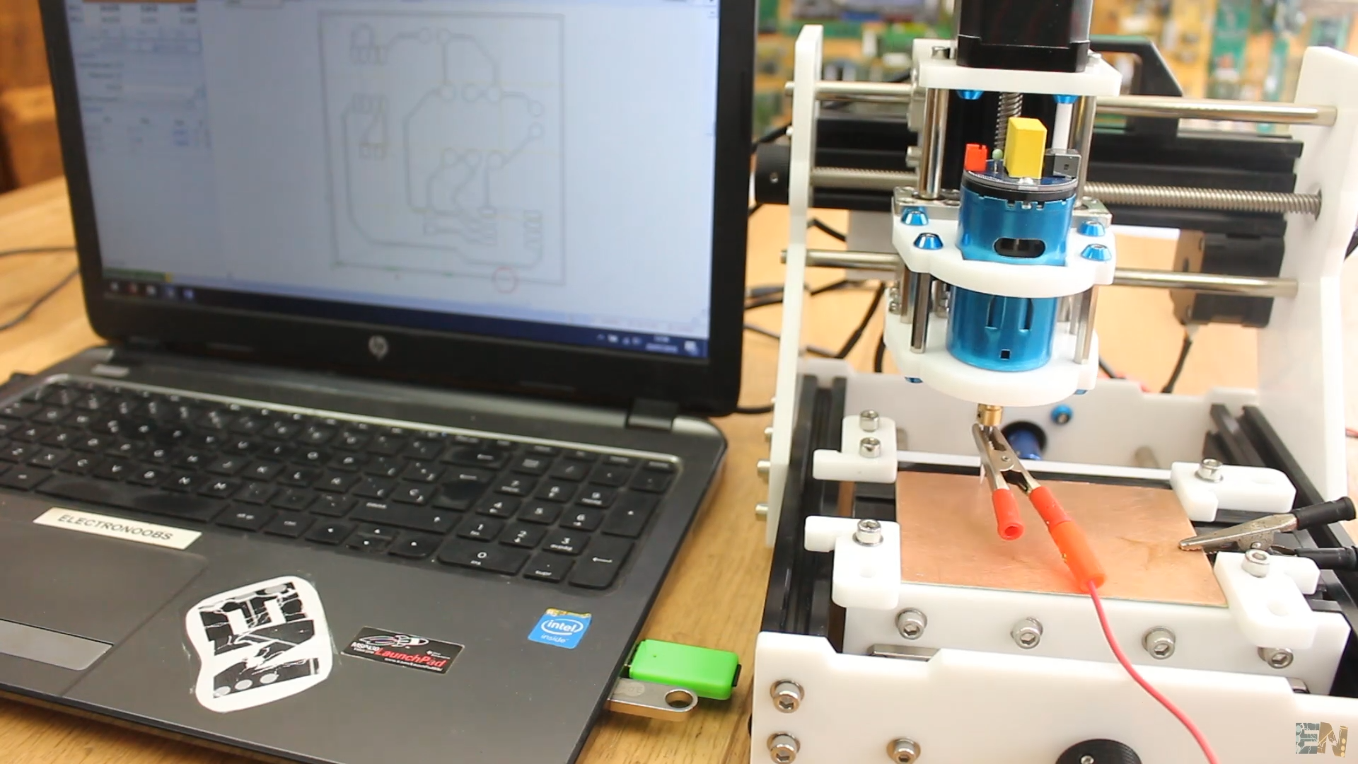
The machine will start scanning and the error values will be printed on the screen for each point. This might take a while. Once finished, click this zero button and we are done. I go up 1mm on the z axis, disconnect the alligator clips of the probe and then connect back the spindle power cable. Now I press start and observe the magic.
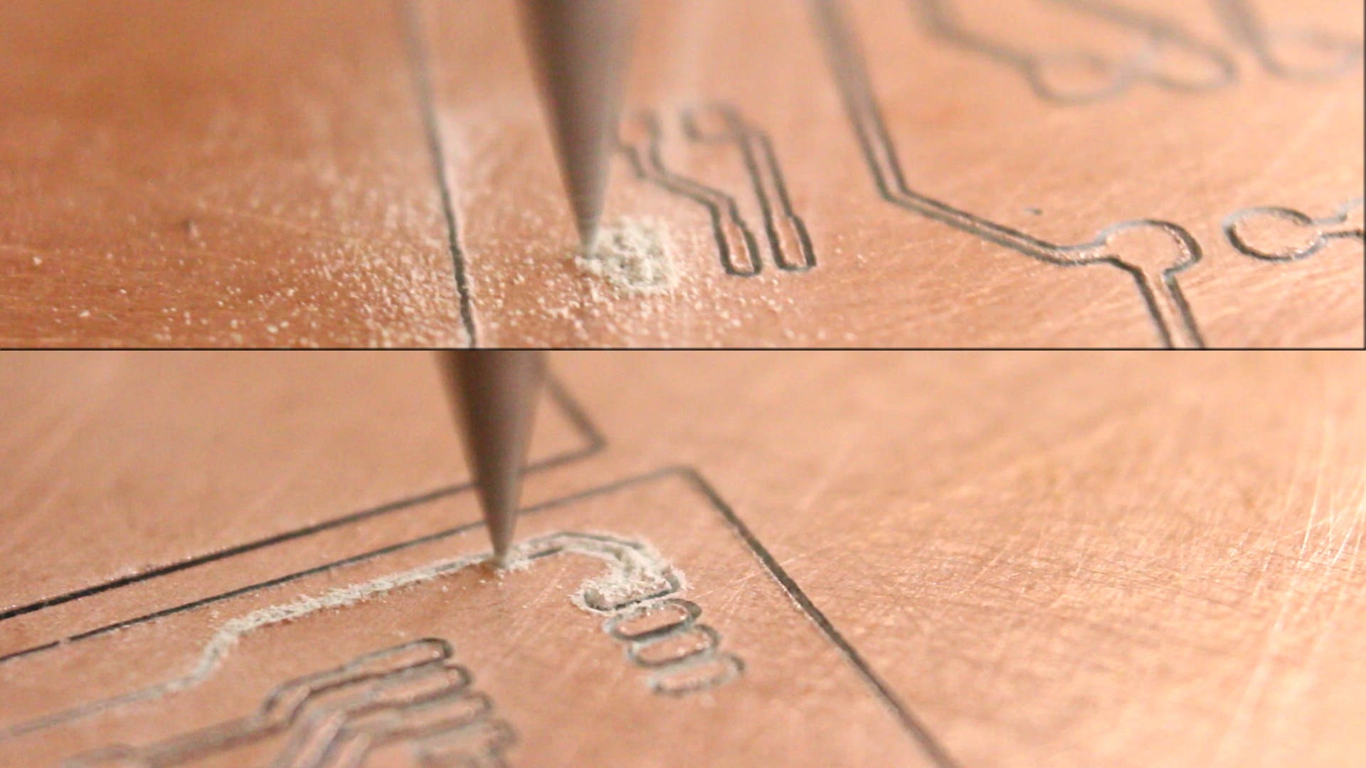
The machine starts milling the tracks of my circuit. The first test had some depth problems so I’ve increased the milling depth a bit and the second circuit turn out quite good. The tracks are 0.22 mm and I could even use SMD components.
More examples
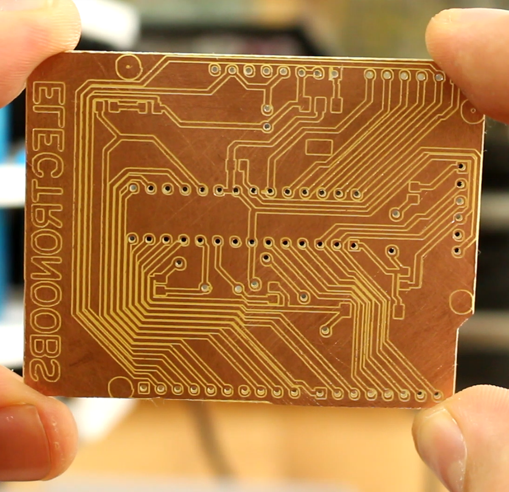
I've milled an Arduino UNO layout. We have it in the next photo. The process took me around 20 minutes including milling, drilling the holes and cutting the board outline. The board looks nice and after testing for shorts, pass another time some sandpaper and clean it I’ve soldered the components and this is the final board. I have to say that for first test it turn out quite well.
The board look messy because I hat do use a lot of flux so solder would stick only to the pads I wanted. I have the Atmega chip, the 16MHz crystal, smd capacitors , voltage regulators and the female pins around. I’ve uploaded a code using the FTDI programmer and now, whrn I power the board with 12 volts, the LED is blinking but it is on the other side of the board.


