
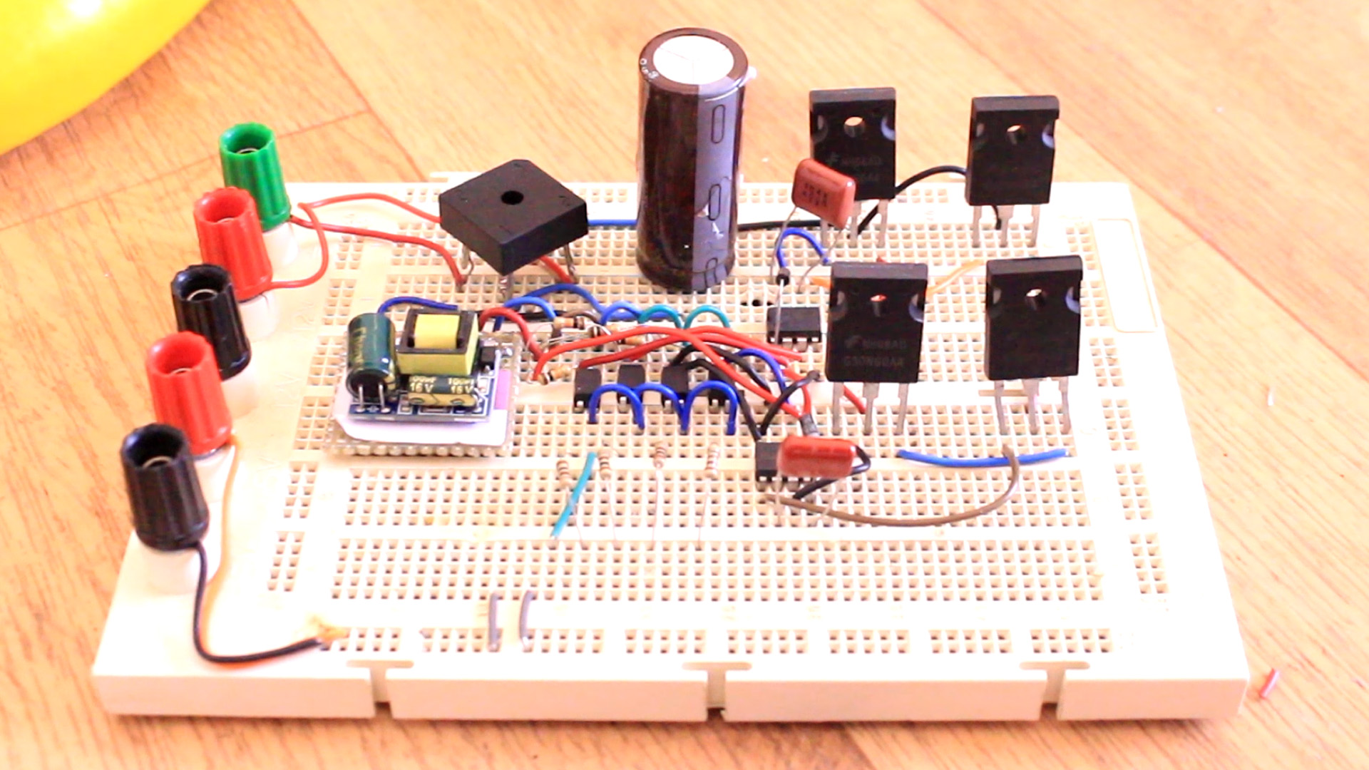
This is a prototype on a Variable Frequeny Driver or VFD. With this circuit we would control the frequency of high AC voltage and by that the speed of induction AC motors. Since we work with high voltage, is a dangerous circuit
VFD stands for variable frequency driver and we use this circuit to control the speed of AC motors since by controlling the frequency of the input voltage of an AC motor, we control the speed of that motor. The idea is simple but to get good results is not. This circuit has both rectifier and inverter circuits and for that see the past tutorial on inverters and learn how the work. But basically, we have 230VAC input and we first rectify that and get DC voltage of 330V and store it inside capacitors of high voltage. Then we use the inverter circuit and create AC voltage from that 330V DC. The output could be a square wave or maybe a SINE wave in case of using SPWM signals. For that see more on this SPWM inverter tutorial. So why rectify the voltage and then make it AC again? Well, in this way, we are in control of the output frequeny because we will control the inverter IGBTs bridge. In case of the 230VAC from our home outlet is just a fixed frequency, usually on 50 or 60Hz. So, that's what we try to do today.
Let's see what we need to create the circuit of this project. We need parts to rectify the signal with a full bridge rectifier, then to make the inverter with IGBTs and for that we also need MOSFER drivers, we need optocouplers to separate the voltage and the Arduino. To get 12V from 230V AC I'm using some very small converter modules. In this way we can supply the arduino and have the high and low voltage separated since the converter module is using a transformer and that's a good way to separate voltages.
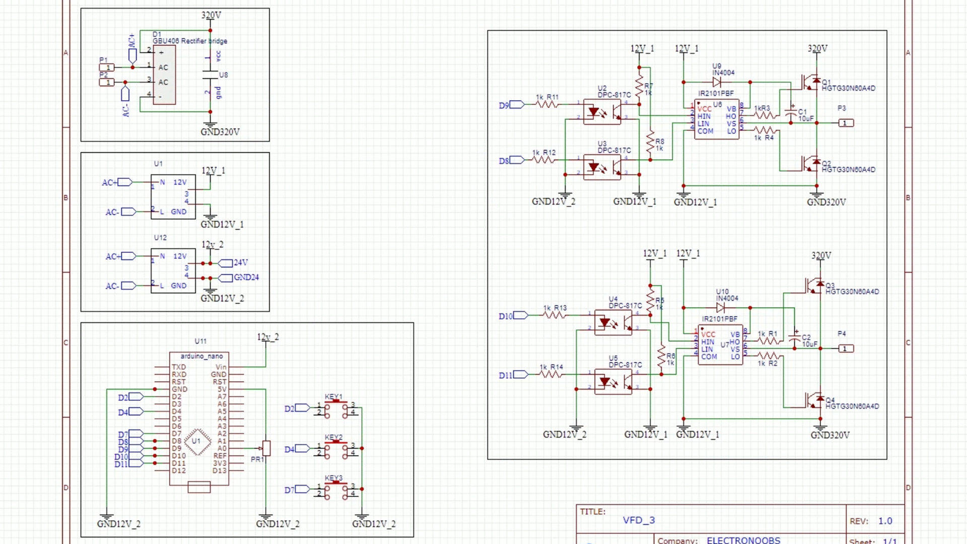
And I say propsoed schematic because as I told you before this is not fully tested yet. But this is my proposed scheamtic. The idea is to first get two 230VAC to 12VDC converters and by taht obtain two 12V supplies (12V_1 and 12V_2). One is for the Arduino and the other one for the optocouplers and the MOSFET drivers. I want that in order to separate the voltage of the Arduino and the High voltage of the IGBTs bridge.
Once we have 12VDC, we can take a look a the rectifier. Using a full bridge rectifier we get 330V and store that in the U8 capacitor. This must be a high voltage capacitor. Once we have 330VDC stored, we use the IGBT bridge to create high voltage AC square waves at the output. To control the IGBTs, we use the MOSFET drivers and to separate the signal from the Arduino and the drivers, I want to use the optocouplers.
The code for this shoule be quite simple. We create pulses at the gate of the IGBTs with the Arduino. These pulses will have a certain frequency. We read the potentiometer or those 3 push buttons and according to that we increase or decrease the switchins speed of the IGBTs.
The testing code is more than easy. We will just create some square waves by switching the gate of the IGBTs in diagonal in the H bridge. So, when the left top and the right bottom IGBTs are high we put to low the other 2 and then after a small delat we do the oposite. The delay will give the frequency so we change the value of that delay with the potentiometer. And that's it. Copy or download the code from below.
int Delay;
int pot = A0;
int LT = 9;
int RT = 10;
int LB = 8;
int RB = 11;

void setup() {
  pinMode(pot,INPUT);
  pinMode(LT,OUTPUT);
  pinMode(RT,OUTPUT);
  pinMode(LB,OUTPUT);
  pinMode(RB,OUTPUT);

  digitalWrite(LT,LOW);
  digitalWrite(RT,LOW);
  digitalWrite(LB,LOW);
  digitalWrite(RB,LOW);
}

void loop() {
  //We read analog input from the potentiometer and map the value from 4000us to 25000us
  Delay = map(analogRead(pot),0,1024,4000,25000);     //1/2*5 = 100Hz and 1/2*25 = 20Hz
  digitalWrite(LT);
  digitalWrite(RB);
  delayMicroseconds(Delay);                           //Delay of T/2 in us
  digitalWrite(LB);
  digitalWrite(RT);
  delayMicroseconds(Delay);                           //Delay of T/2 in us
}
I can't tell you the final results because I had a short circuit and the huge high voltae capacitor almos blow up. I will post more about this circuit soon. So, for now this circuit is not tested. Sorry for that.


