
Crystal or ceramic resonator and then we have the oscillator. What is the difference between these 3 elements, why we need them in our circuits, how each of these works and what configurations do we have. In this post we will see all that. I’ll try to explain the main differences between crystals and ceramic resonators, and what different circuits we have for oscillators. Each part will have a few examples in such a way that you will understand how we could use these elements and why we need or not, extra components. Maybe like this you will know which is the best choice when you will be designing your own circuits.
A resonator is a device or system that exhibits resonance or resonant behavior. That is, it naturally oscillates with greater amplitude at some frequencies, called resonant frequencies, than at other frequencies. The oscillations in a resonator can be either electromagnetic or mechanical. Resonators are used to either generate waves of specific frequencies or to select specific frequencies from a signal. Musical instruments use acoustic resonators that produce sound waves of specific tones. Quartz crystals is used in electronic devices such as radio transmitters and quartz watches to produce oscillations of very precise frequency. We also have the ceramic resonator and the LC resoantor tank. Later we will see the circuits for that.
Let’s start with crystals. As the metal sheet before, this component also has a mechanical resonance but of a piezoelectric material. A piezoelectric material will also create a small voltage each time is strucked, because of the deformation of its atomic crystal structure. So, in this case, not only that we get our resonating frequency related to that specific crystal, but we also get a detectable voltage drop and that can be connected to our circuits. But once again, this oscillation will drop and we need do struck the crystal again in order to create a stable on and on oscillation. For that we need an oscillator circuit that we will see in moment.
The ceramic resonator can do the same thing, which is to exhibit resonance behavior, but there are a few differences between crystal and ceramic resonators and the most important one is the frequency tolerance on heat temperature changes. The ceramic resonator utilizes a frequency within the electrical component but unlike the crystal which has a frequency tolerance of 10 up to 30 PPM or parts per million, a ceramic resonator carries a 0.5% or 5,000 PPM frequency tolerance, so, is generally used in microprocessor applications where absolute stability is not that important.
So, for better stability, use a crystal resonator. But as we have seen before, a crystal resonator can’t work by its own. It needs the oscillation circuit so let’s see a few examples.
The most-simple oscillation circuit is probably the multi-vibrator which has only a few simple components such as resistors, capacitors and two transistors. This is called a RC oscillator and it doesn’t need a crystal. This below is the circuit and if we apply voltage on the resistors, the capacitors will charge up and that will turn ON a transistor on one side, that will empty the capacitor, then the other side will charge up and so on.
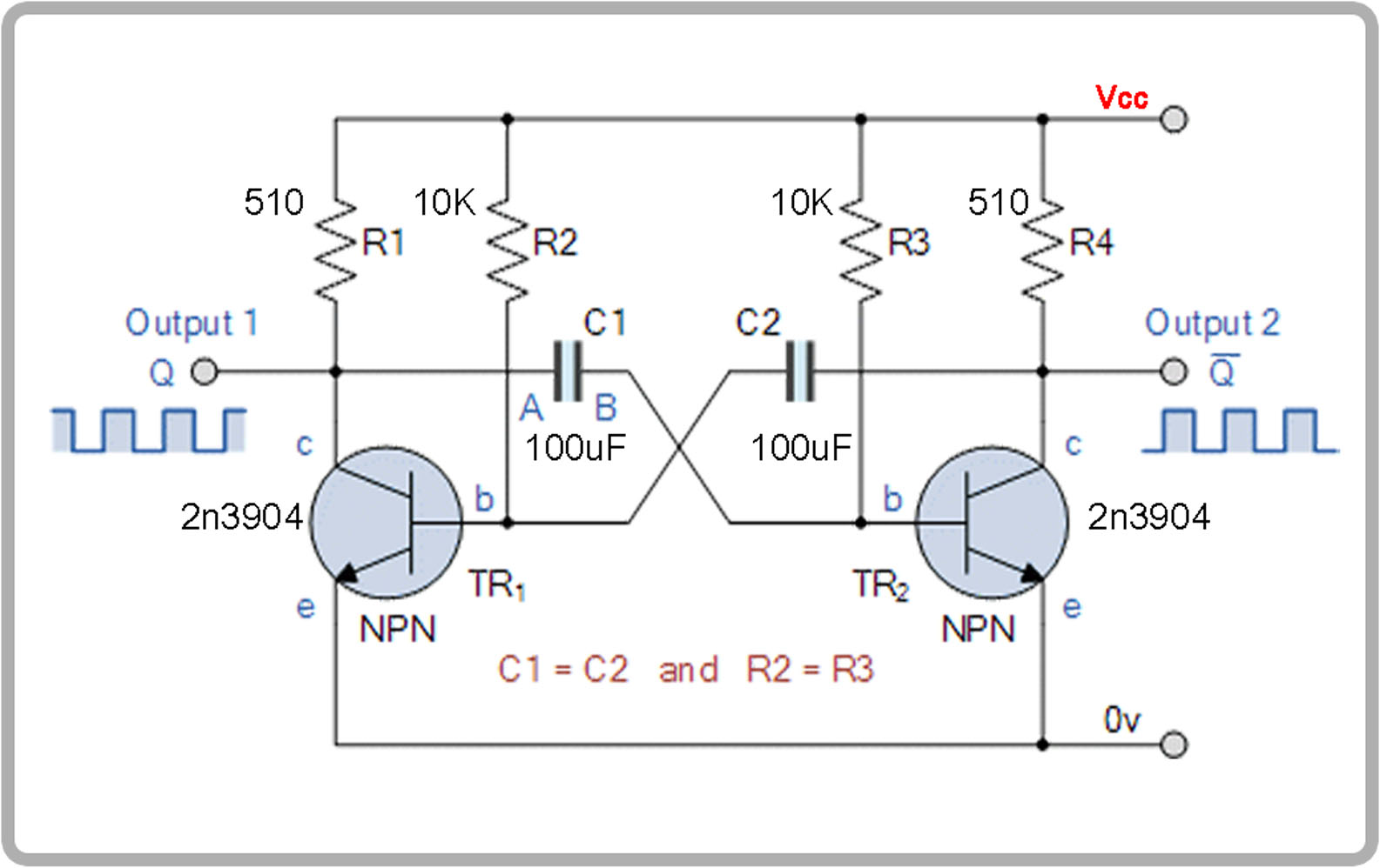
This will create an oscillation signal and the frequency is given by the capacitor and the resistors values. I mount this on a bread board and add two LEDs to the charging resistors and as you can see, we now have an oscillation between the two sides and a good squared wave that we could use. If we change the capacitor or resistor values, we could make the oscillation faster or slower.
But this solution can’t get to very high frequencies, and also, the stability is not that good. So, if you want very stable circuits, we need a better solution.
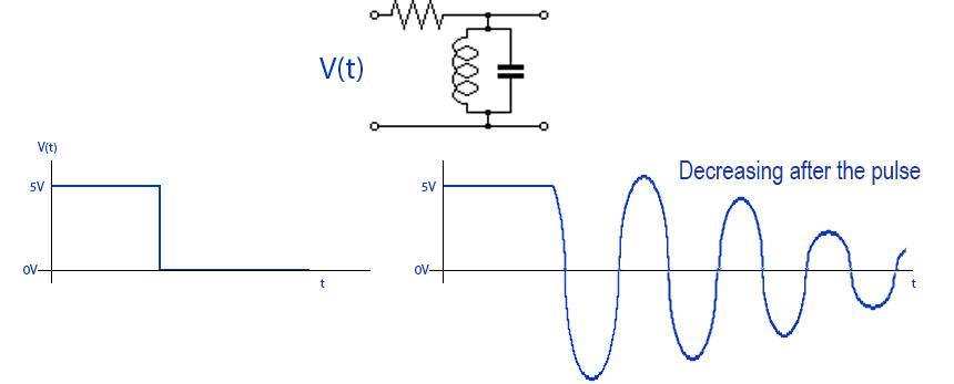
Another oscillating circuit is the one that use resonators. Before we look at the ceramic and crystal resonators, let’s take a look at the LC oscillator, so we need a coil and capacitor. Remember from the inductance meter tutorial, that an LC tank will resonate at its natural frequency. See that tutorial for more information. But when we electronically struck an LC tank, the capacitor will rapidly charge up and then when it wants to discharge, the coil will build up a magnetic field
This will collapse, and charge back the capacitor but with opposite polarity. Then again, it will discharge and do this over and over again, creating oscillations. This will oscillate at the resonance frequency which can be given by the capacitor and inductor coil values. So, by knowing the values, we can create the signal we want. Check all the formulas you need to calculate the resonating frequency of an LC tank and more.

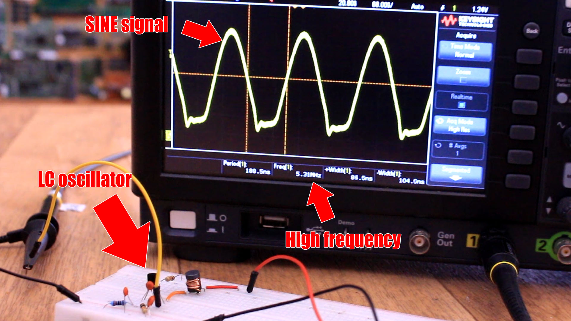
But if we take a look on the oscilloscope at an LC tank resonating, we can see that after a few oscillations, the amplitude is decreasing till we have no more oscillations. That’s due to internal losses because of the circuit resistance that will lose power into heat. So as in case of the crystal and ceramic resonators, we have to constantly struck this LC tank with a voltage pulse in order to keep the oscillations going.
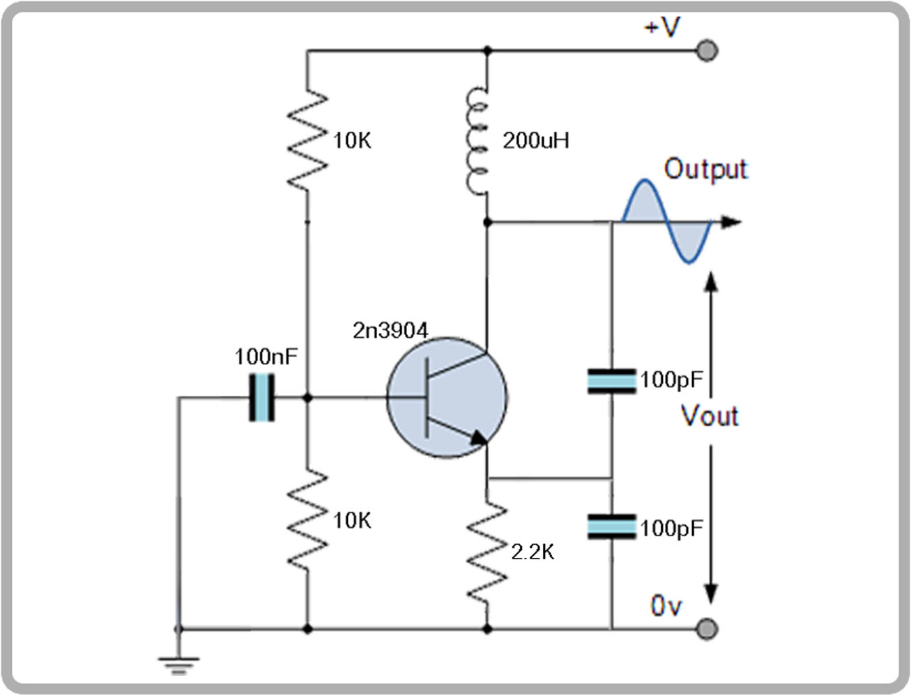
For that we connect the output of this LC resonator above, to the input of an amplifying component, in this case an BJT transistor, see scheamtic above. The transistor will get on and off each reversed pulse, and by that cut or apply voltage to the LC tank and constantly make it resonate. This will give us a nice oscillating signal that we could use with our circuits, microcontrollers and so on. With the correct values, we could get up to MHz for the signal, but this circuit is very sensible to noise, temperature change, parasitic capacitance and resistance added by wires connections and so on.
So, finally, for very stable frequencies, we could add the crystal resonator instead of the LC tank, and get very accurate signals. Remember that we had to constantly hit this crystal with a voltage pulse in order to make it resonate. I make a similar circuit as before and mount everything on the breadboard. But instead of the LC tank, I place the crystal resonator and again, the signal is amplified and then we have constant oscillations. In this case I’m using a 16MHz crystal so the signal it of 16Mhz.
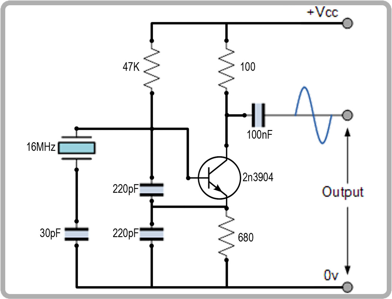
Usually, we have capacitors around the crystal in order to resonate with the crystal inductance and cause the crystal to oscillate on its fundamental resonant mode. The reason we have two capacitors in series is to create a network that creates a 180 degree phase inversion at resonance, because the amplifier (inverter) has a 180 degree phase inversion between its input and output. This makes the loop gain have a net phase shift of 360 degrees, which is what causes it to oscillate.
The crystal can be of different materials, but the most common for this purpose is quartz, which is a mineral composed of silicon and oxygen atoms in a continuous framework of silicon–oxygen tetrahedra. By changing the internal structure, the size of the crystal, the length and 3D shape, we can get different frequencies and usually crystal resonators can go from KHz up to hundreds of MHz. The ceramic resonator is the same but with a piezoelectric ceramic material instead, and as said before, is not that stable.


