


Well, guys, let’s see the next example, the voltage follower. The photo below is the configuration for this example and as you can see we have now added a connection from negative input to output that is called feedback, a negative feedback.
One of the laws before was that the OPAMP will try to make the voltage at the negative input equal to the one at the positive input. By other ideal law, we know that no current could flow throw the input rails. So, the only way to change the voltage at the negative pin here, is towards the feedback.
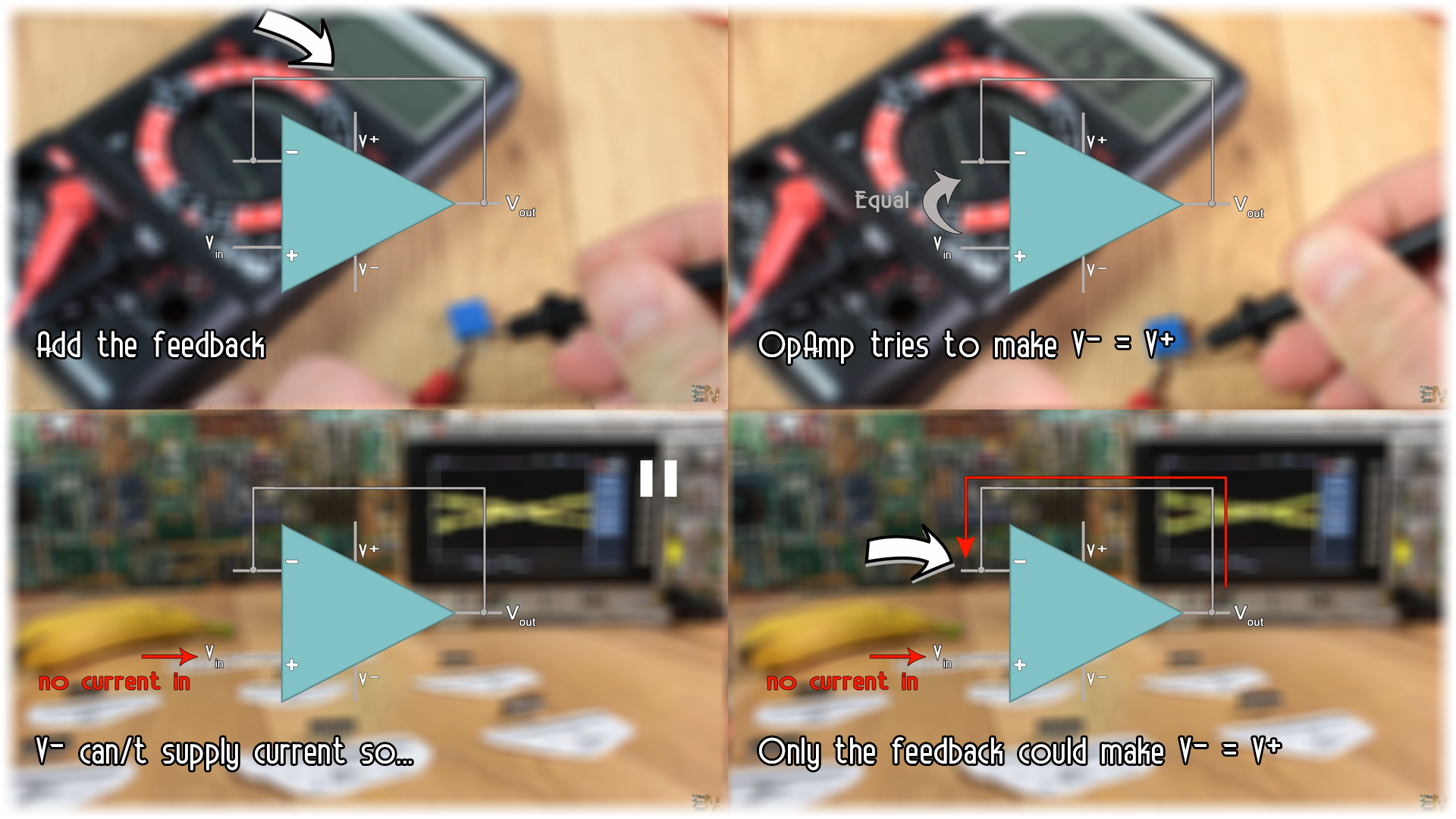
Let’s imagine we put 5 volts at the positive input. The OPAMP, internally will do all it has to do in order to put exactly 5 volts at the output, and at the same time at the negative input. So now we have the same value at the output as at the input, that’s why it is called flower.
But you must wonder, what stupid thing is this. Why apply 5 volts to obtain 5 volts as well. Well imagine this. Imagine that you have a circuit that works at let’s say 3 volts. Now let’s say that you want to connect to that circuit and measure the voltage. If you put a low impedance probe to it, current will flow thru the connected rail, and by that we change the circuit value and we don’t want that. We don’t want to measure the wrong values. We want the real one. For that, between the measured circuit and our connection we put a voltage follower. In this way, no current will flow towards the measuring device and by that we won’t affect the measured circuit but we still have the real voltage value at the output.
Done, above I’ve mounted this configuration on my breadboard and applied a sine wave to it. As you can see the output is the same as the input and no current is flowing towards the OPAMP.
Ok guys, let’s take a look at the next configuration, the inverting one. Since we have just looked at the voltage follower circuit, instead of having just a simple connection between the output and the negative input, let’s add a resistor to that connection and another resistor at the negative input and connect the positive input to ground. Now, let’s apply real values so we could better understand how this works.
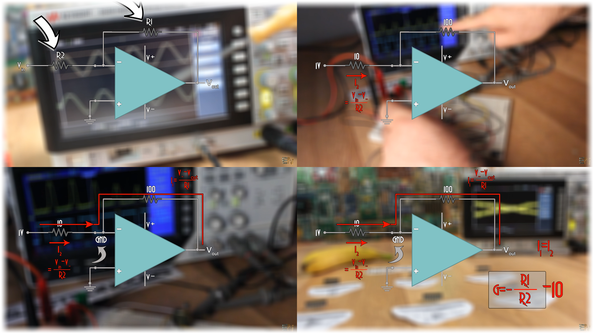
If the first resistor is 100 ohms and the second is 10 and we apply 1 volts to the input, this will happen. A current will flow through R2. That current value is the input minus the voltage at the negative input point divided by R2. But the voltage at the negative point must be the same as the one at the positive input, in this case ground. We call this virtual ground, since we don’t really have a ground at the negative pin.
Since no current could flow towards the OPAMP, the only route that the current could take is thru the negative feedback rail. This current value could also be expressed like the difference between the negative pin and output rail divided by R1. Since the negative input is ground, all we are left with is that the negative output value divided by R1 is the current value. But this is the same value as current 1.
From these two equations we get that the gain, which is expressed as the output divided by input is negative R1 divided by R2. And there is our amplification.
R1 is 100 and R2 is 10 so the gain is -10 in this case. So, if we apply our 1 volts at the input, we get negative 10 at the output and vice versa. That’s why it is called inverted, since the output is inverted to the input and just by changing the resistors values we can change the gain of the amplifier.
I mount this configuration on my breadboard with resistors values of 100 and 10 kilo ohms. I supply positive and negative 12 volts to the amplifier and apply a 1 volts peak to peak sine wave at the input.
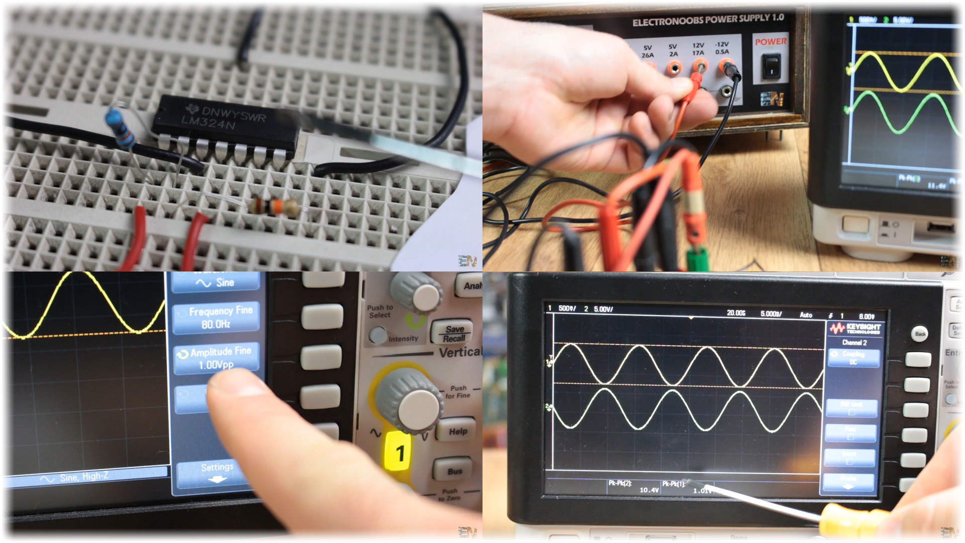
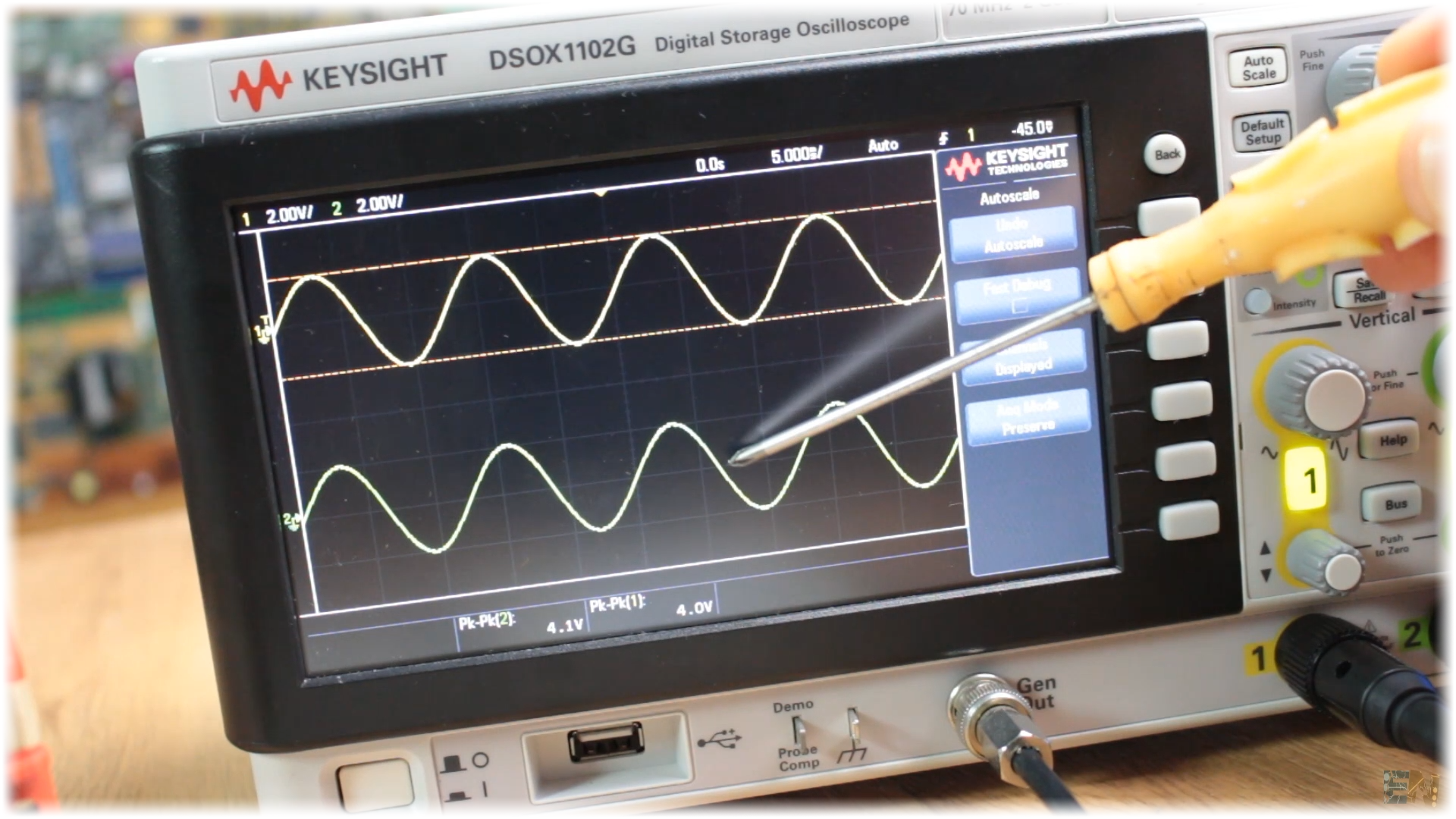
Now on the oscilloscope, the yellow line is the input and the green the output. As you can see the output is 10 times bigger and also inverted, when the input is rising, the output is falling and vice versa.
Finally let’s talk about the noninverted configuration. This below is its schematic. Now the positive input pin is our main input of the circuit and the feedback is still connected at the negative input. Now, as before, the negative pin value is the same as at the positive input, in this case let’s call it Vin. The current through R2 is Vin minus GND divided by R2. And the current through R1 is Vout minus Vin divided by R1. But we know once again that these two currents are equal. So, solving these two equations we get that the gain of this configuration is 1+ R1 divided by R2.
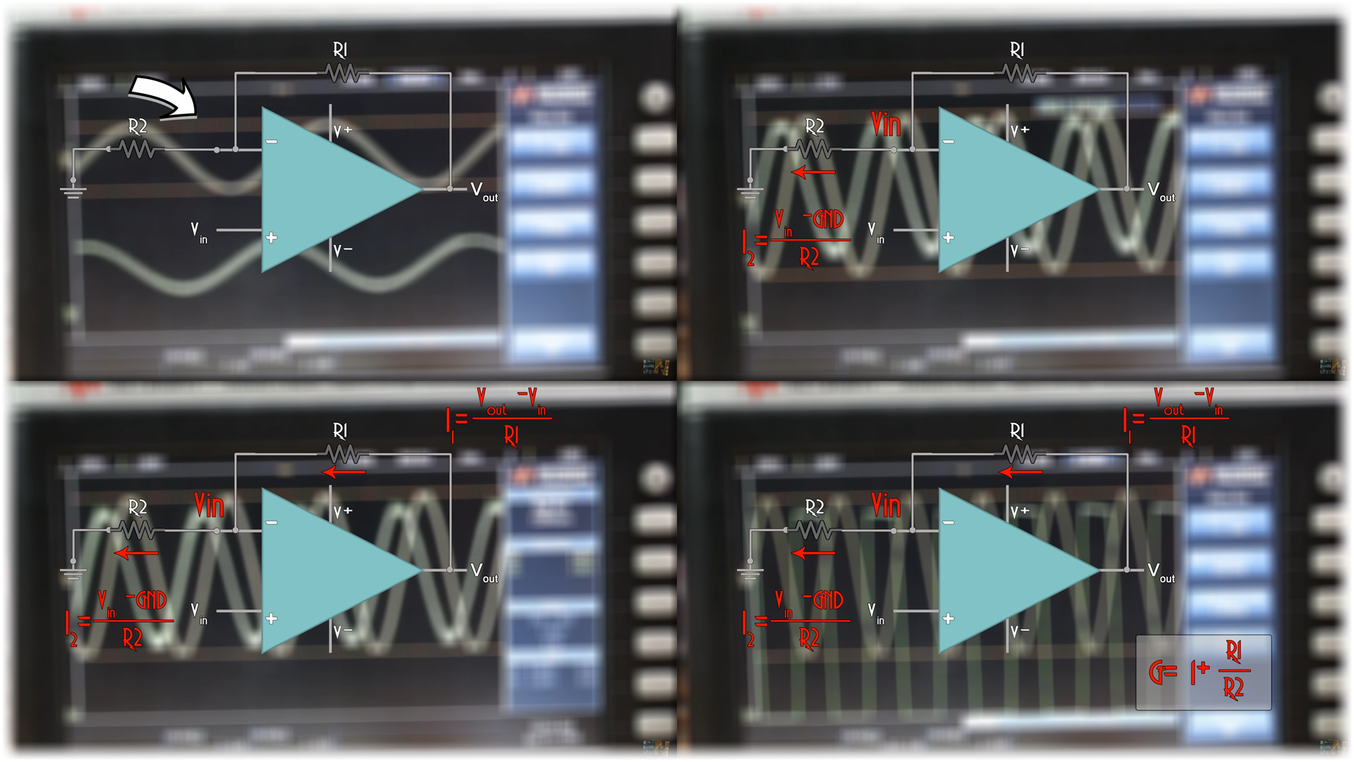
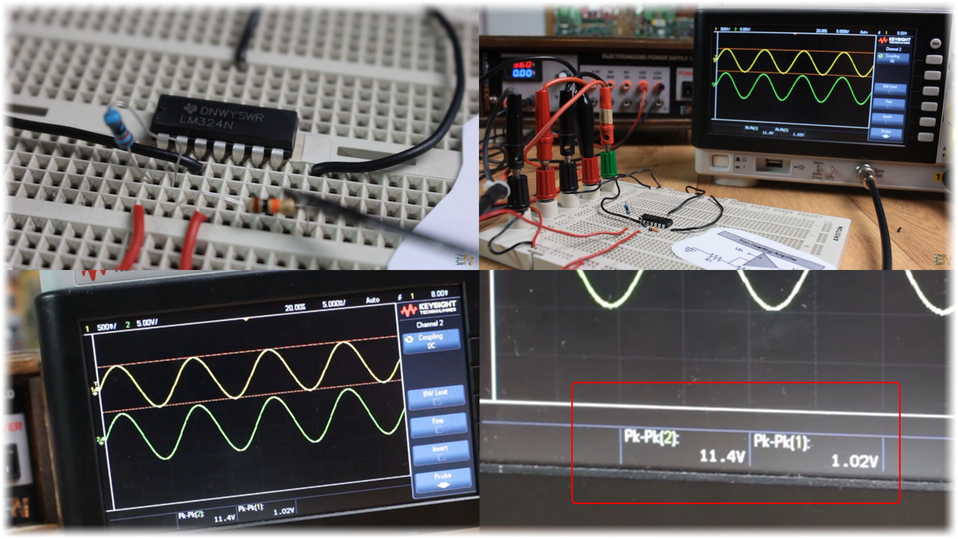
I mount this example on the breadboard using 100 and 10 kilo ohms resistors for R1 and R2. I supply power the amplifier and once again, apply a sine wave at the input of 1 volt peak to peak. On the oscilloscope, again the input with yellow and the output with green and we can see that the output is 11 times higher and that it is not inverted. So, depending on what you want for your project, just use one configuration or the other. You could even connect two amplifiers in a cascade and have double amplification or double inverted signal, so the output won’t be inverted.
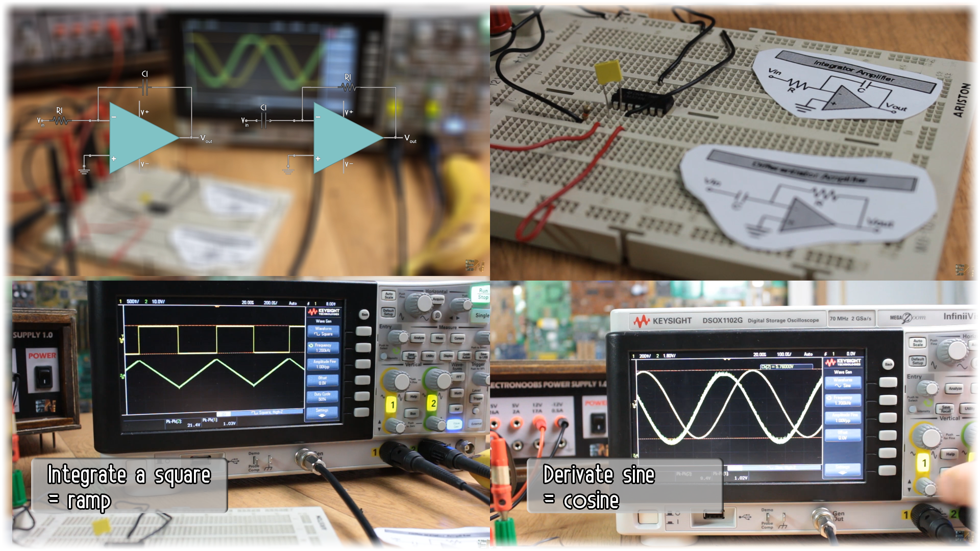
Well guys, just as an extra, I’ll show you the schematics for the differential and integral configuration. As you can see now, we have some capacitors as well. With these configurations, by applying a square wave at the input, you could easily obtain a ramp. Also, the derivative of a sine wave is a cosine wave as you can see here on my oscilloscope.
There you go my friends, now you know a bit more about basic OPAMPS. One interesting configuration is a PID controller where we use the Integrator, differential, inverter and summer configuration of the OPAMPs and by changing the resistors and capacitors values, we can tune the PID response.
Well guys, there you have it, stay tuned for the next basic components tutorial where we will take a look at another component. Have in mind that I’ve explained only the ideal laws of the OPAMPS, in real life this won’t be exactly like this since each component will have its limitations such as no infinite input impedance, output current limitation, bad commune input amplification and so on.
Also, check my videos where I’ve used OPAMPS like the RPM meter, the AC current probe to amplify a magnetic field sensor signal, I even made a crude 3 bit ADC using OPAMPS, so even this tutorial is very basic I hope you’ve learn something about OPAMPS.
Help my projects here: patreon.com/ELECTRONOOBS
Instagram here: instagram.com/electronoobs
Facebook here: facebook.com/Electronoobs
Leave your comment below.


