About me
  History
  Let's learn
  Contact us
  Arduino tutorials
 Circuits tutorials
  Robotics tutorials
 Q&A
Q&A Blog
Blog  Arduino
  Circuits
 Robotics
  Modules
  Gadgets
  Printers
  Materials
  3D objects
  3D edit
  Donate
  Reviews
  Advertising


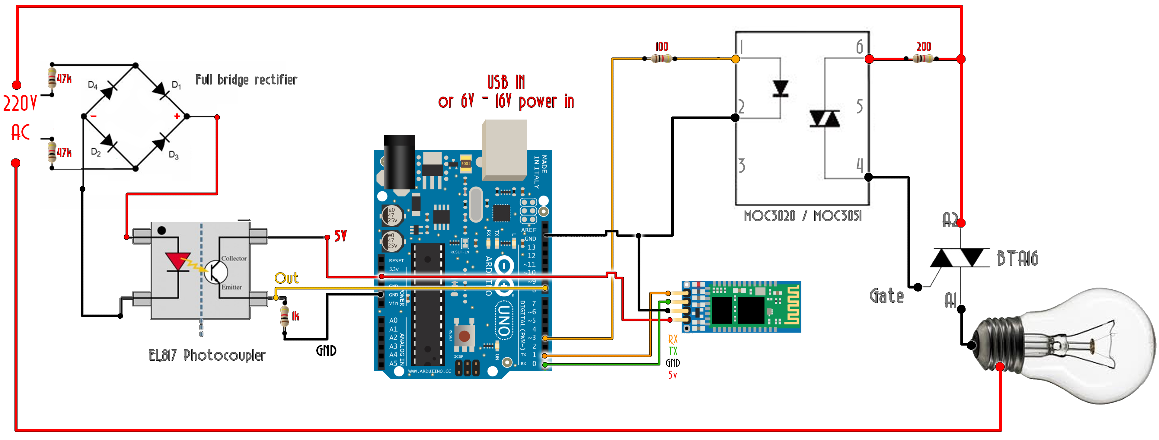
Arduino AC TRIAC dimmer - Potentiometer
Download the .zip file below. Open it on your Arduino IDE.
This code is for the schematic with the BT connection for the power control. Read all the comments in the code.
/*TRIAC control with potentiometer; author: ELECTRONOOBS
 * Subscribe: http://www.youtube.com/c/ELECTRONOOBS
 * Tutorial: http://www.ELECTRONOOBS.com/eng_circuitos_tut20.php
 * Thank you
*/
int detectado = 0;
int valor=0;
int last_CH1_state = 0;


void setup() {
  /*
   * Port registers allow for lower-level and faster manipulation of the i/o pins of the microcontroller on an Arduino board.
   * The chips used on the Arduino board (the ATmega8 and ATmega168) have three ports:
     -B (digital pin 8 to 13)
     -C (analog input pins)
     -D (digital pins 0 to 7)
  //All Arduino (Atmega) digital pins are inputs when you begin...
  */

  PCICR |= (1 << PCIE0);    //enable PCMSK0 scan
  PCMSK0 |= (1 << PCINT0);  //Set pin D8 trigger an interrupt on state change. Input from optocoupler
  pinMode(3,OUTPUT);        //Define D3 as output for the DIAC pulse
  Serial.begin(9600);       //Start serial com with the BT module (RX and TX pins)
}

void loop() {
   //Read the value of the pot and map it from 10 to 10.000 us. AC frequency is 50Hz, so period is 20ms. We want to control the power
   //of each half period, so the maximum is 10ms or 10.000us. In my case I've maped it up to 7.200us since 10.000 was too much
   if(Serial.available()>0)
   {
      valor = map(Serial.read(),0,255,10000,10);
      //In my case I've used valor = map(Serial.read(),0,255,7000,10); for better results
   }
    if (detectado)
    {
      delayMicroseconds(valor); //This delay controls the power
      digitalWrite(3,HIGH);
      delayMicroseconds(100);
      digitalWrite(3,LOW);
      detectado=0;
    }
}


//This is the interruption routine
//----------------------------------------------

ISR(PCINT0_vect){
  /////////////////////////////////////               //Input from optocoupler
  if(PINB & B00000001){                               //We make an AND with the pin state register, We verify if pin 8 is HIGH???
    if(last_CH1_state == 0){                          //If the last state was 0, then we have a state change...
      detectado=1;                                    //We haev detected a state change!
    }
  }
  else if(last_CH1_state == 1){                       //If pin 8 is LOW and the last state was HIGH then we have a state change
    detectado=1;                                      //We haev detected a state change!
    last_CH1_state = 0;                               //Store the current state into the last state for the next loop
    }
}