
 About me
  History
  Let's learn
  Contact us
  Arduino tutorials
 Circuits tutorials
  Robotics tutorials
 Q&A
Q&A Blog
Blog  Arduino
  Circuits
 Robotics
  Modules
  Gadgets
  Printers
  Materials
  3D objects
  3D edit
  Donate
  Reviews
  Advertising


Sensored ESC - Homemade
Brushless motor sequence
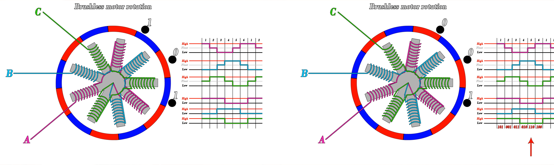
This is the sequence that we have to make in the photo below. We enter through A and exit on B. Then we enter on C and exit on B and so on with a total of 6 different steps. But how do we know when to switch to the next step. Well, here comes the job of the sensors so let’s place those on our motor representation.
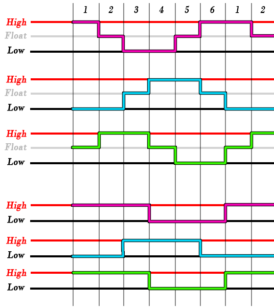
Right now, we are in the first step of the sequence, so we have negative, a positive and another negative magnet in front of the sensors. That will give us the 1 0 1 output. We keep on spinning and the A hall sensor will now pass to 0 since now the positive magnet is in front of it. The other two are still the same. So now we have a 001 which is the next step of the sequence. During a full rotation we will have this this sequence of the hall sensors outputs.
All we have to do, is to detect this steps with a microcontroller and control the triple phase bridge.
Part 3 Triple phase bridge
This is the triple phase bridge schematic. On the top side we have some PMOSFETS, and on the bottom part some NMOSFETS since the source is connected directly to ground. In the past tutorial we have used a MOSFET driver to control the transistors since the microcontroller works at 5V and we will apply a higher voltage than that to the MOSFETS.
I won’t use a driver this time in order to keep it simple and just understand how this works. Instead I’ll make my own driver with a BJT and a pullup at the gate of each MOSFET.
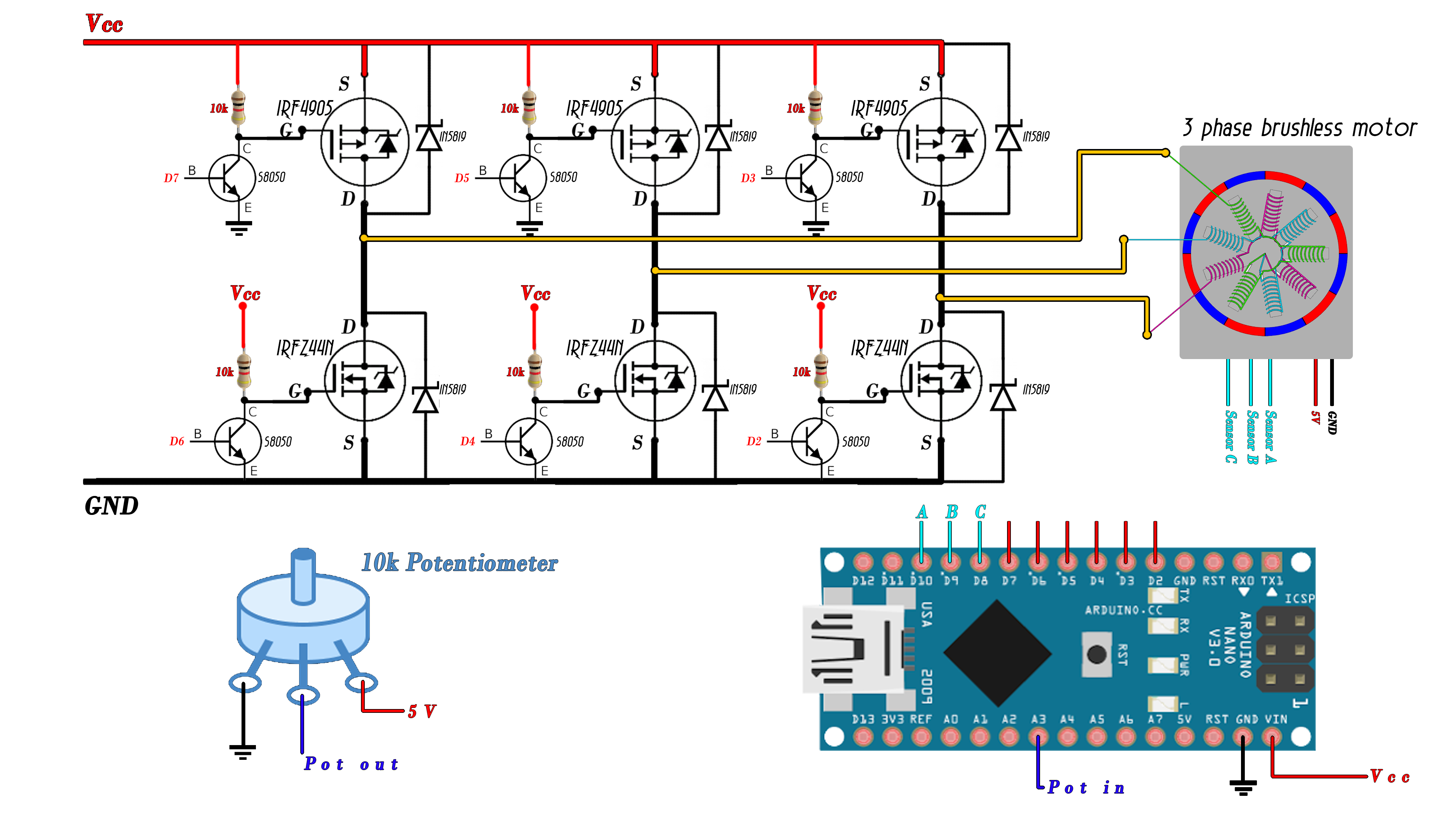
When the top A MOSFET and bottom B is activated, current is flowing through A and exit on the B coil. Next, we activate the top C MOSFET and leave the bottom B activated, so now current is flowing from C to B and so on.
As you can see on each step we control two of the MOSFETS, on from the top part of the bridge and one from the bottom part.
In the photo above we haev the schematic of my sensored electronic speed controller. I mount it on my bread board and test it. To make the sensor read and MOSFET switch, I’ll use the Arduino. I connect the A, B and C sensor outputs to pins 8, 9 and 10 of the Arduino. Then pins 7, 6, 5, 4, 3 and 2 to the 6 MOSFETS of the bridge. I connect a potentiometer on analog input A3 in order to control the speed of the motor. I will later supply 12 volts to the main input of the bridge.
Part 4 The code
We are ready for the code so let’s take a look. I define the sensors pins as inputs. Next, with the registers below I configure pins 8, 9 and 10 to create interrupts. Each time one of these pins will change its state, we go to the interrupt vector.
void setup() {
  //Define sensor pins and potentiometer as inputs
  pinMode(pot,INPUT);
  pinMode(SensorA,INPUT);
  pinMode(SensorB,INPUT);
  pinMode(SensorC,INPUT);
  pinMode(pwm_pin,INPUT);

  PCICR |= (1 << PCIE0);    //enable PCMSK0 scan
  PCMSK0 |= (1 << PCINT0);  //Set pin D8 trigger an interrupt on state change.   sensor A
  PCMSK0 |= (1 << PCINT1);  //Set pin D9 trigger an interrupt on state change.   sensor B
  PCMSK0 |= (1 << PCINT2);  //Set pin D10 trigger an interrupt on state change.  sensor C
}
In the interupt vector we detect the sequence and decide the fase of the rotation depending on the state of the hall sensors. If we have a 101 we switch to the first step, if we have a 001 to the second step and so on as in the table before with a total of 6 steps.
In the void loop we create a case that will switch two MOSFETS on for each step of the sequence depending on what step we are on that sequence. In this case I use port manipulation instead of digital write since that is a lot faster.
I read the potentiometer speed and create the delay between each step according to the potentiometer read value mapped with a value from 1 to 4000 microseconds. Read all the comments in the code in order to understand more.
ISR(PCINT0_vect){
  //This part will run any time any of the sensor pins will change its value.
  if(  (PINB & B00000101) && fase == 6  ){
    fase = 1;
  }

  if(  (PINB & B00000100) && fase == 1 ){
    fase = 2;
  }

  if(  (PINB & B00000110) && fase == 2 ){
    fase = 3;
  }

  if(  (PINB & B00000010) && fase == 3 ){
    fase = 4;
  }

  if(  (PINB & B00000011) && fase == 4 ){
    fase = 5;
  }

  if(  (PINB & B00000001) && fase == 5 ){
    fase = 6;
  }
}
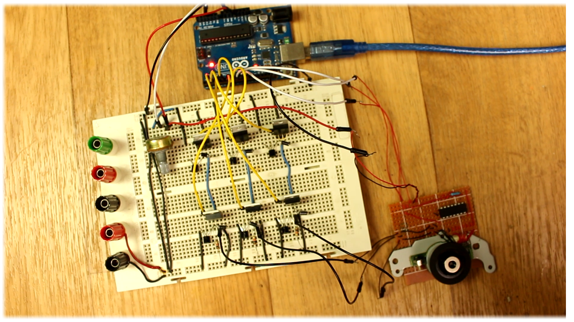
I upload the code and make sure all the connections are made. I supply the circuit and now the brushless motor is spinning. I connect the probe of my oscilloscope to one of the MOSFET gates. As you can see we have a square wave signal. If I try to slow down the motor with my hand, the width of the pulse will automatically adjust in order to match the speed of the motor and that’s due to the hall sensors feedback.
Also, using the potentiometer I can set the speed of the motor by changing the delay between each step of the sequence.
But usually, commercial electronic speed controller use a PWM signal input with a width range between 1000 and 2000 microseconds to control the speed. For that, in the code, I set pin 11 as the PWM input. In the interruption vector I detect each time that pin change its state and measure the time between each pulse. I map that value to a delay from 3000 to 10 microseconds. You are able to make tests and change this value according to your motor. Also, the motor will start spinning only for values of the PWM input higher than 1070 which is a very commune value.
Go to next part and see how to improve the code.