About me
  History
  Let's learn
  Contact us
  Arduino tutorials
 Circuits tutorials
  Robotics tutorials
 Q&A
Q&A Blog
Blog  Arduino
  Circuits
 Robotics
  Modules
  Gadgets
  Printers
  Materials
  3D objects
  3D edit
  Donate
  Reviews
  Advertising


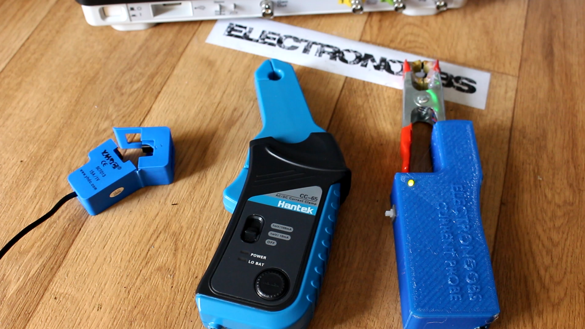
DC non invasive current clamp for oscilloscope DIY
2.0 DC current clamp
So, a constant magnetic field won’t induce current into the winding so the output will be 0. So how we could measure and observe DC current?
In this type of probe we will also use a ferrite core that will carry the magnetic field. The core is provided with an air gap that will hold a sensor, in this case a hall-sensor, which measures the magnetic flux in the core.
So now we don’t need an AC current anymore since we could directly measure the magnetic flux value.
The current in the primary wire, which is the measured wire, will magnetize the core. This magnetic field is measured with the sensor.
Another way and a better way to measure DC current is with a compensation winding. But that’s a little bit more difficult to mount and calibrate. But its principle goes like this.
The primary winding it is also the measured current carrying wire and is inserted through the core opening. There is also a secondary winding, but now it functions as a compensation coil. The core is provided with an air gap that holds a sensor, once again a hall-sensor, which measures the magnetic flux in the core.
2.1 Build the DC current clamp
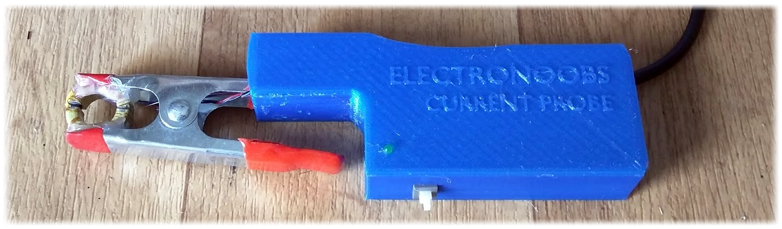
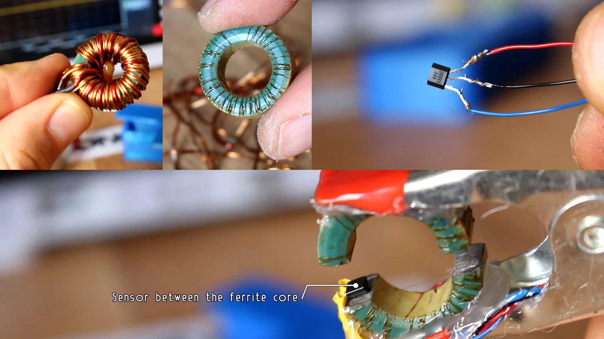
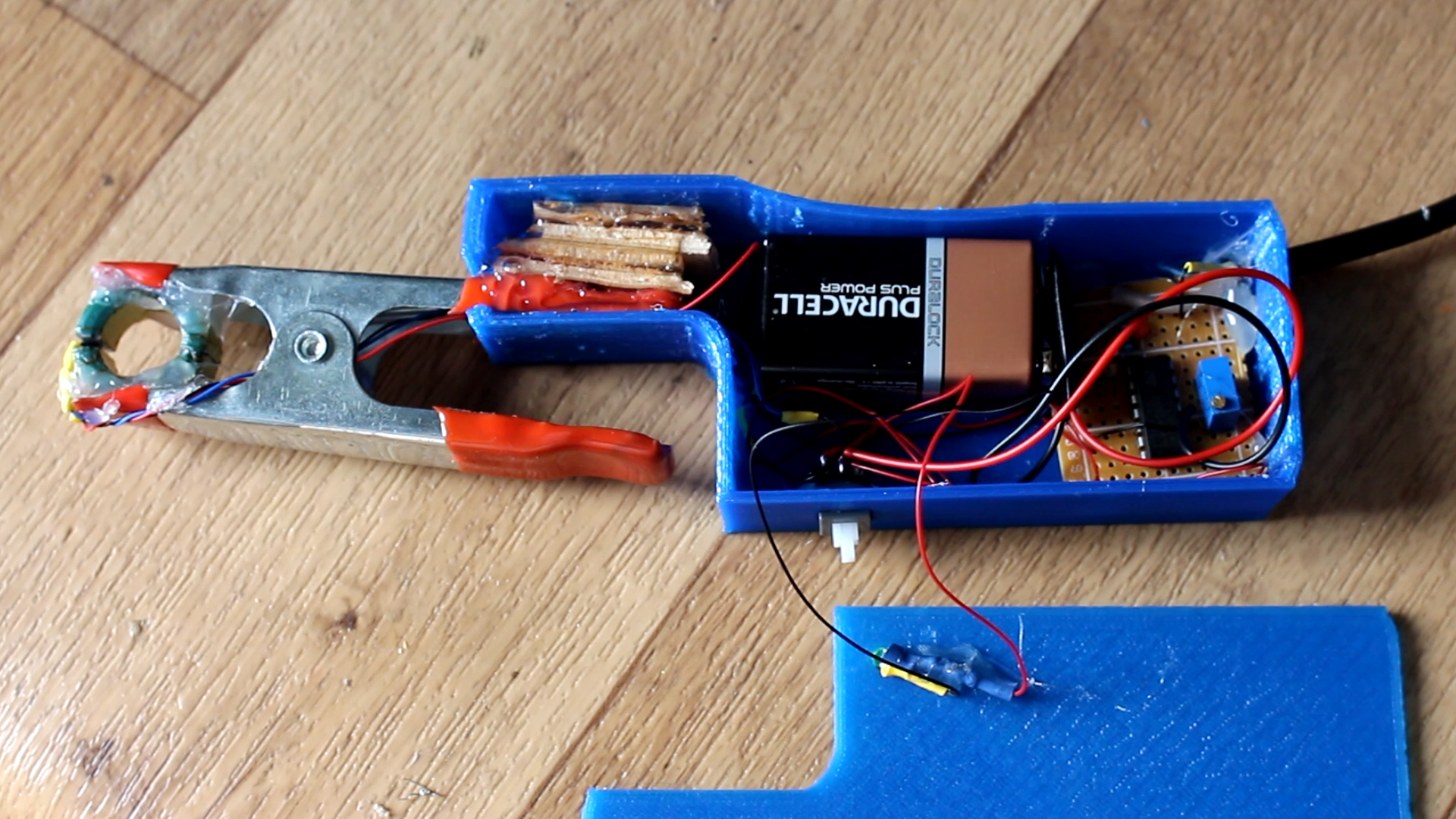
So, using an alligator clamp like this I’ll build my own DC current clamp together with a 3D printed case. You could download my design from a link below. I will use this circular core that I’ve got from an old power supply that doesn’t work anymore. Cut it in half and glue it in place on the tip of the clamp. Be patient while cutting the core because it’s quite fragile. Finally polish the cut and make sure the core will close ok with the sensor in between.
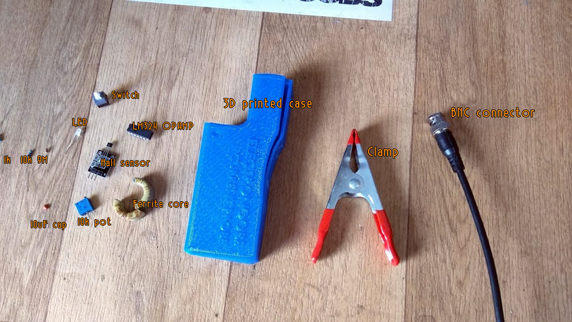
See the full part list here:
Now I prepare the Hall sensor and glue it in place between the gap of the ferrite core. I make sure that the clamp could close with no problems and that the ferrite core is as tight as it can. I connect the sensor to ground, 5 volts and the signal output wires with the black, red and blue wires.
Connect the output to the oscilloscope to test it out for now. As you can see if I approach this magnet to the sensor the output will rise. So just like that, if the magnetic field inside of the core will increase due to the passing current through the measured wire, I could easily measure the current value. But there is a problem. The magnet creates a very powerful magnetic field. But the current passing through the wire won’t. The magnetic field will be very small. So, we will definitely need to amplify the output from the sensor. For that I’ve use and operational amplifier with the inverted configuration and a gain of 100.
I’ve used the LM324 OP amp which is quite bad, but sorry for that, it’s the only one I’ve got for now till the new ones will arrive. You could use any other amplifier but make sure you will make the proper connections. In the inverted configuration, the gain is given by these two resistors.
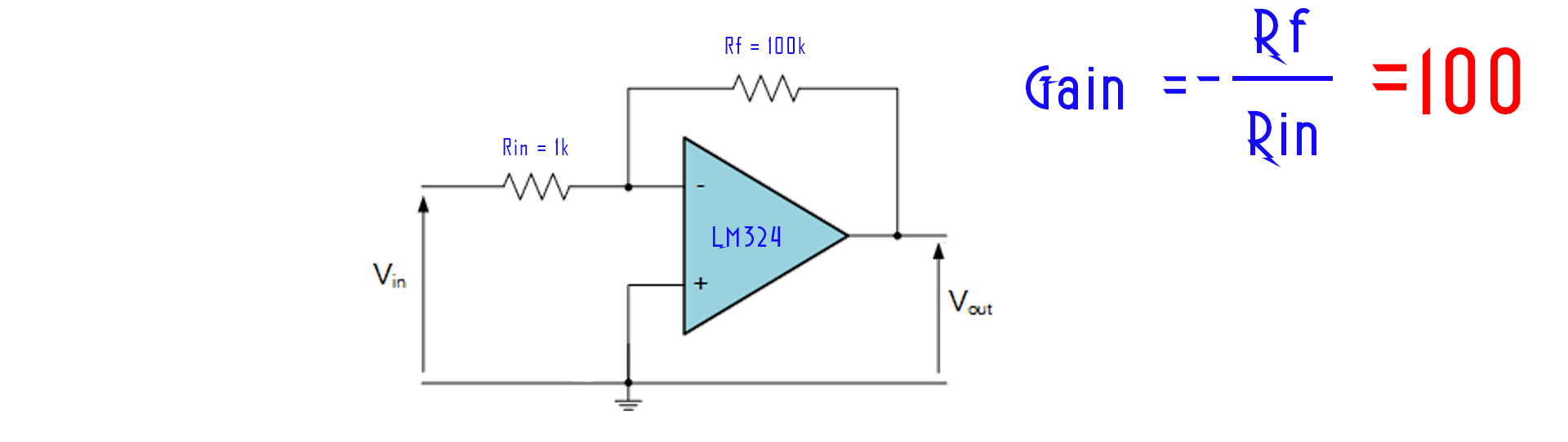
In my case one of 100k ohms and one of 1k ohm equal to a gain of 100. I’ve created this circuit with a small potentiometer in order to calibrate the output. I will also need to supply the circuit so I will use a 9V battery. Both the amplifier and the hall sensor could withstand that voltage so no regulator is needed.
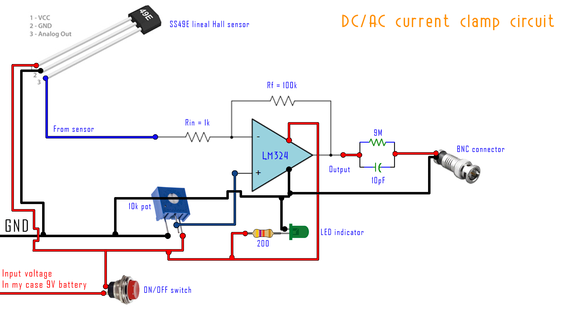
Now I mount everything on a drilled pcb and connect the wires from the Hall sensor. To the output I’ll connect an oscilloscope probe connector like this with a small filter circuit in between as any probe has. The filter circuit is included in the final schematic. The 3D printed case has holes for a switch and a LED indicator. You could download the final schematic from a link below.
Download the schematic here:

I place all the components inside of this 3D printed case. You could download the 3D printed case from the link below and follow the isntructions to print it. I've used PLA material.
Download the 3D case here:
Before I close it I have to calibrate the probe. For that I apply a current value that I control through the wire. Clamp the probe to it and adjust the potentiometer.
2.2 Calibrate the DC current clamp
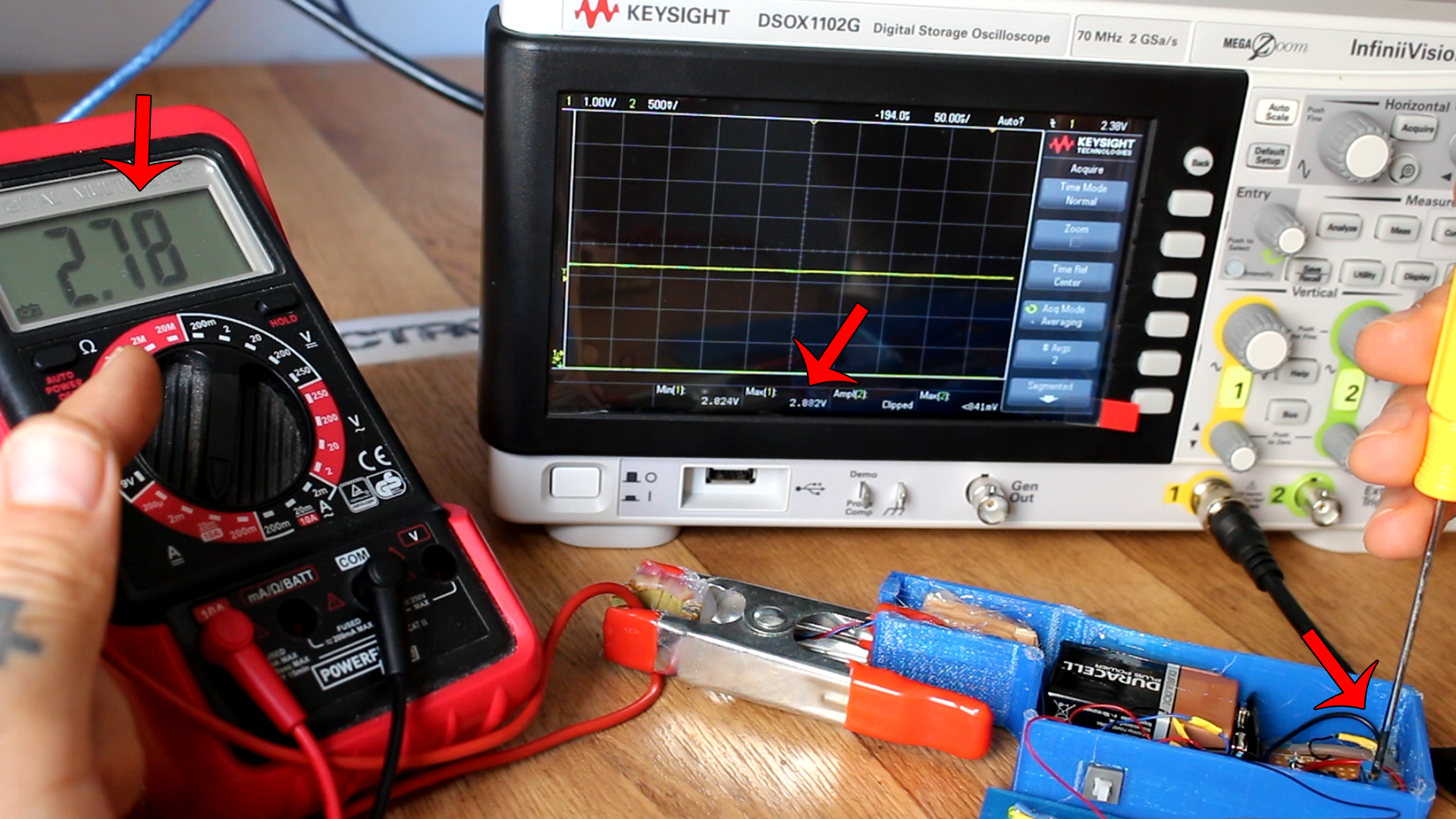
Clamp the probe to it and adjust the potentiometer. For example, I apply a current of 2.8 amps through the main wire. Now I adjust the potentiometer till I have a voltage of 2.8 volts on the oscilloscope. In this way, using a lineal sensor we should have a decent relation between the measured current and the output voltage.
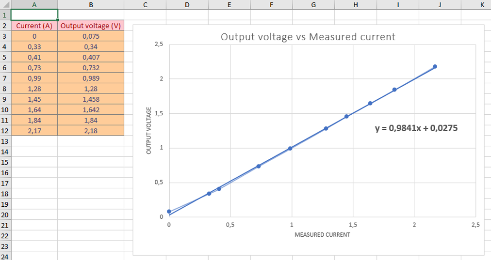
Now, after some measured results I get the scale of the clamp and created this second graph. I know that I’ve got a scale of 100 and a maximum output voltage of 9V so the probe will saturate at around 9 amps value. To increase precision you could always turn the wire multiple times around the core and the precision will increase proportionally. The clamp works. I’ve got the same value measured with the multimeter as the one on my oscilloscope if I apply the corresponding scale. The good thing of this type of clamp is that I could still observe AC current with it and that’s awesome because the magnetic field is proportional to the current that passes to the wire.
That’s it. We have seen how to create the AC current clamp with the basic transformer and the DC current clamp with the hall sensor. That’s it for today lesson. This project is just an example and it could always be improved once you know the basics. If you enjoy my tutorials and want to support me, please, check my Patreon page.
Help me on Patreon