About me
  History
  Let's learn
  Contact us
  Arduino tutorials
 Circuits tutorials
  Robotics tutorials
 Q&A
Q&A Blog
Blog  Arduino
  Circuits
 Robotics
  Modules
  Gadgets
  Printers
  Materials
  3D objects
  3D edit
  Donate
  Reviews
  Advertising


DIY power suppy
Power supply made with an old PC power source
If you work with electronics you will definitely need a power supply for your projects. Usually when your project is already finished that power supply could a battery, maybe a transformer like this one or even a small power supply like this here that I’ve used for my mini CNC milling machine. But while you are testing and you have to switch between voltage values or control the current limit it is way better to have a bench power supply with some decent connectors, variable voltage and current and some sort of display to show you the values, either is digital or analog. That’s exactly what we are going to build today.
What do you need?
See the entire part list here:
Old working PC power supply
Buck/boost converter module LINK eBay
2 x 10K ohms potentiometers LINK eBay
2 x plastic knob LINLINK eBayK
1 voltmeter/ammeter module LINK eBay
Banana connectors LINK eBay
2 x toogle switches LINK eBay
1 LED LINK eBay
Wires
Shrinking tubes LINK eBay
Let's build it!
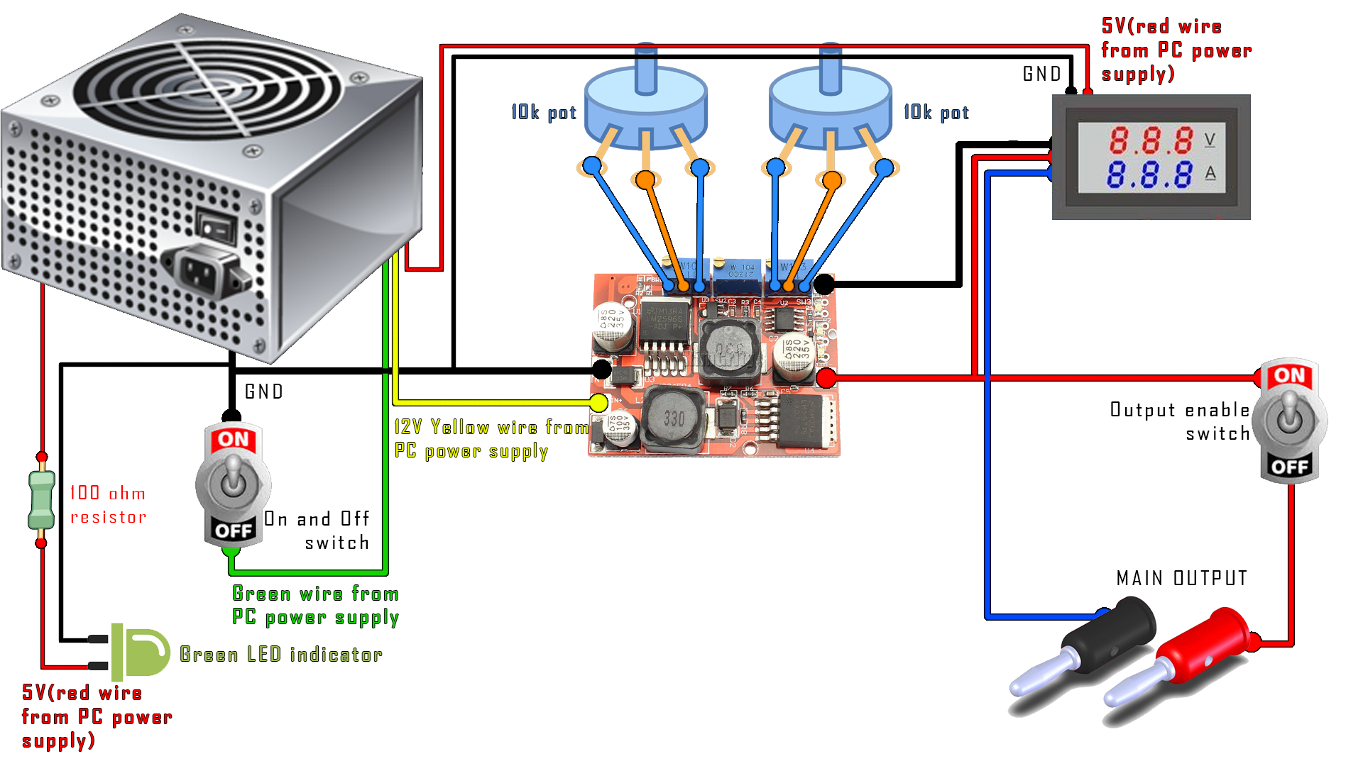
The first thing that we need to do is to test the circuit. Use the next schematic in order to connect all the wires. We should connect 12V from the PC power supply to the input of the boost up boost down convertor. Solder some wires to the 10K ohms potentiometers and connect them in place of the other small 10K potentiometers. The output is connected to the voltmeter module and to the output. We have to add toggle switches to turn on and off the power supply.
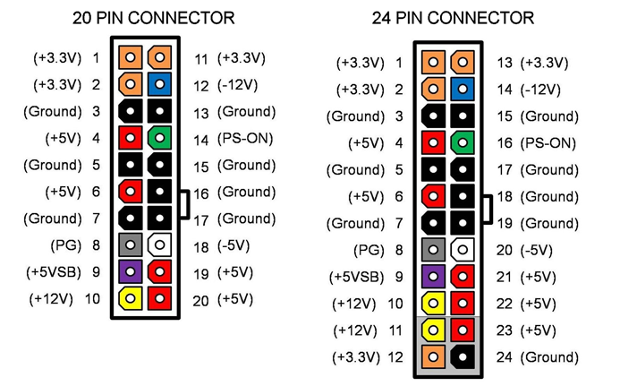
Step 1 - Identify each output
The power supply should have color label for each output. All PC power supplies should have a 3.3, 5, 12 and -12V outputs. We will use the 12V output that usually is the yellow wire. Usually the connection between GND and the green wire powers up the power supply.
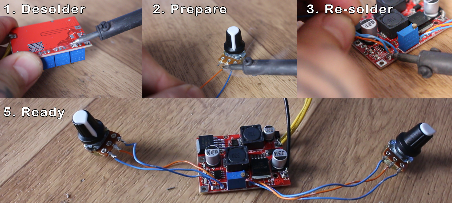
Step 2 - Prepare the converter module
This module has both step down converter and step up converter. That able us, using the 12V as input, to have both lower and higher output voltages. In order to change the voltage and current limit we can use two of those 3 potentiometers that the module board has. Usually the middle one is just a limit set that you shouldn't change. So if we want big nice potentiometers we first have to desolder the small ones. Next we should measure each potentiometer resistance in order to use the same values. Mines are 10K ohms potentiometers so I will use the same. Solder some wires to each pin and the other end of the wires to the converter module board in place of the other small potentiometers.