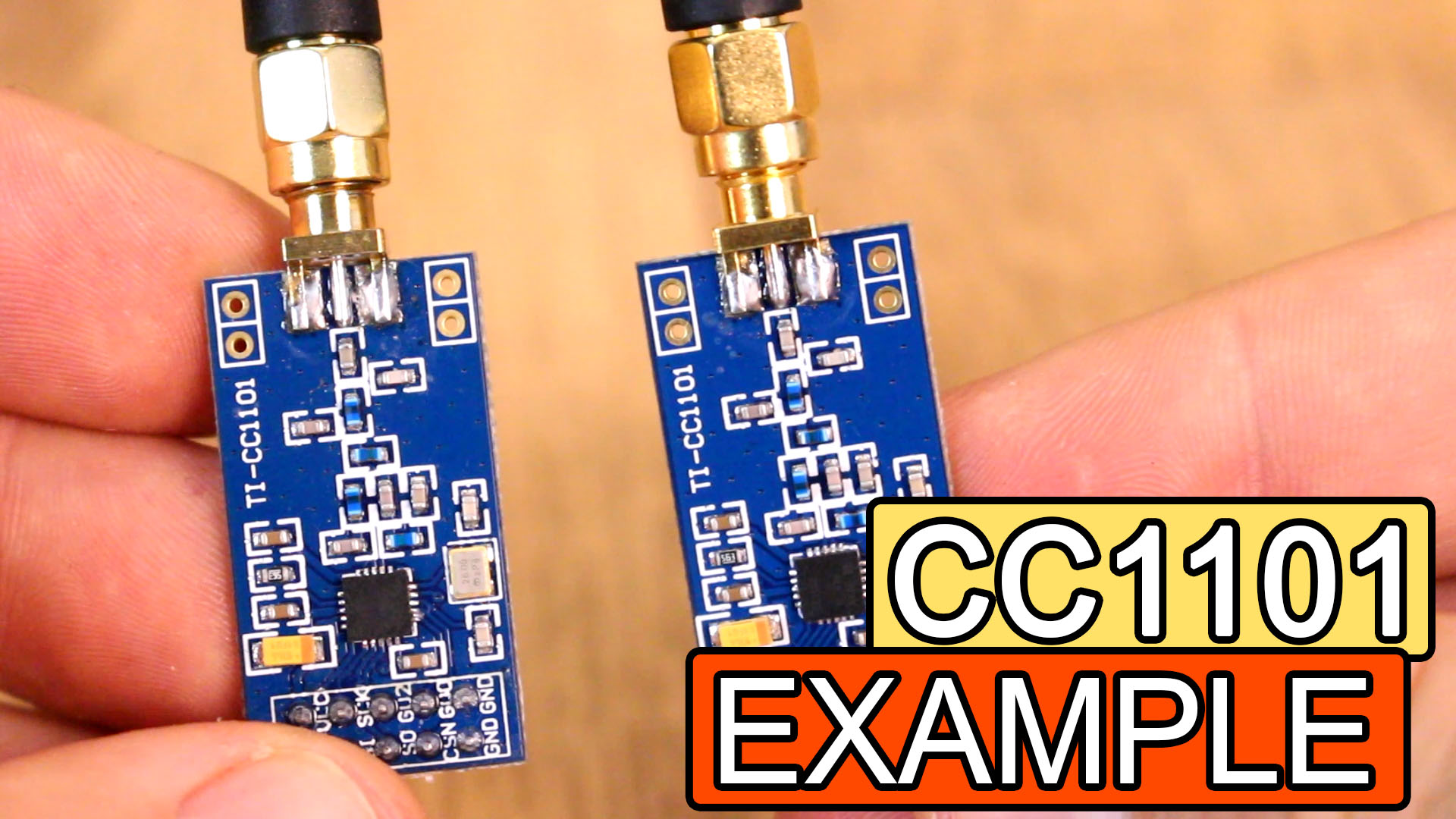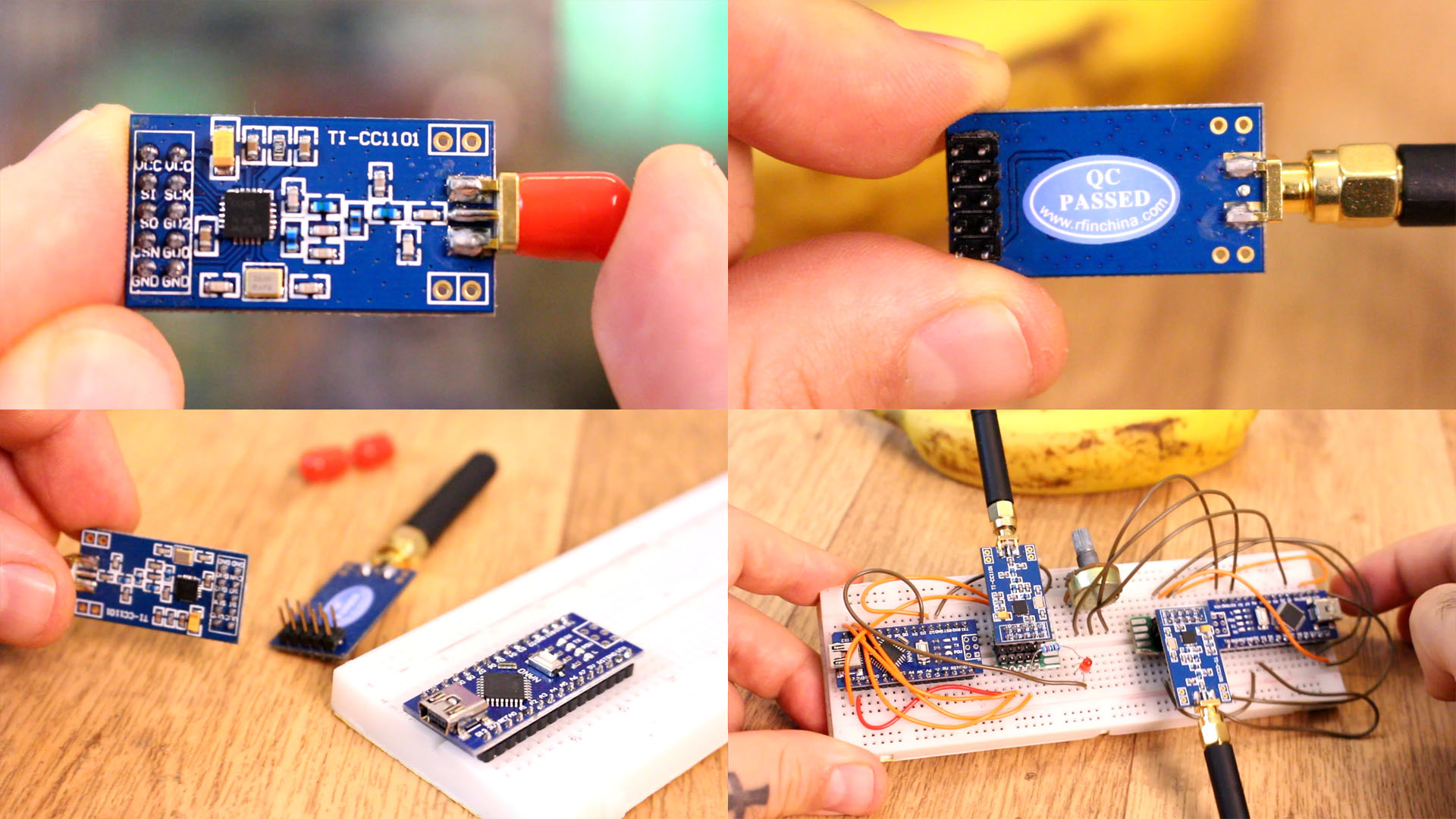

So, I've made a video with some radio modules you could use. In this case we will see the CC1101 radio module with SPI serial communication. See the connections below, download the example code and test if it works. You will need the ELECHOUSE_CC1101 library as well so download that from the links below. You need two modules, an LED and a potentiometer and we will send just one byte of data, 0 to 255 values. The range for this module could be up to 400m abut we need a lot of pins to use this.

Ok, guys let’s move to the CC 11 01 radio module. There are different modules with different frequencies. The frequencies can also be modified. The most popular and also the most used band is the 70 cm band. Again, the module is used via the SPI interface. You might find that the module can not be connected directly to the SPI pins because of the 3.3 Volts operating voltage. And basically this is true, however, during my test I’ve used this with my Arduino and I had no problems. It has a maximum operating speed of 500KB per second and according to the user manual, it could send data up to 500 meters but that depending on the environment, the antenna and baud rate. There are also some small power amplifiers that you could use to increase the transmission power by up to 5 watts. With power amplifiers, you can get over 15 kilometers according to some internet posts I’ve found.

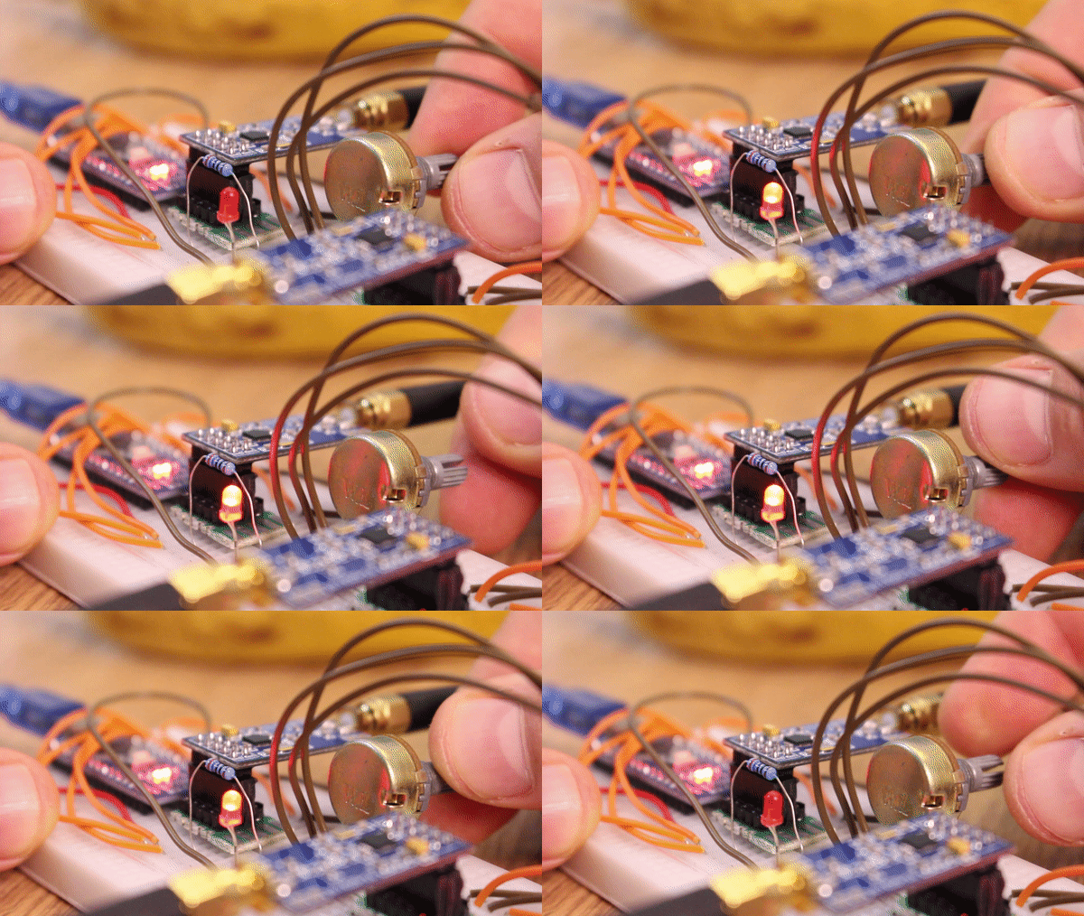
For this module you will need the CC1101 library you will find below in the code link. Make the connenctions for the modules as in the schematic. For breadboard connection you will need a jumper like the one I’ve made with some female and male pins. Download the example code from below and upload those to the Arduinos. You have the transmitter and receiver examples and again, the transmission is working and I can control the LED using radio connection.
The schematic is simple but with a lot of pins. We have 2 Arduino NANO and we will use 3.3V from the Arduino in this case. If this doesn't work, connect an external 3.3V supply and share ground. Anyway, connect the SPI pins and add a potentiometer, and LED and a resistor. Upload the codes below to the transmitter and receiver and read the comments in the code for more. Test if it works and you could change the brightness of the LED using the radio connection.
Here we have the transmitter code. You will need the ELECHOUSE_CC1101 library for this module so download that from the code link below and install it to the Arduino IDE. Uplaod this code to the Arduino with the potentiometer. Read the comments in the code for more. Copy or download the code from below.
/* 1byte CC1101 TRANSMITTER example.
/* Tutorial link: http://electronoobs.com/eng_arduino_tut98.php
 * Code: http://electronoobs.com/eng_arduino_tut98_code1.php
 * Scheamtic: http://electronoobs.com/eng_arduino_tut98_sch1.php
 * Youtube Channel: http://www.youtube/c/electronoobs
// Arduino          CC1101
// GND              GND
// 3.3V             VCC
// D10              CSN/SS   **** Must be level shifted to 3.3V
// D11              SI/MOSI  **** Must be level shifted to 3.3V
// D12              SO/MISO
// D13              SCK      **** Must be level shifted to 3.3V
// D2               GD0
*/

#include <ELECHOUSE_CC1101.h> //Download it here: http://electronoobs.com/eng_arduino_ELECHOUSE_CC1101.php
#define size 1
int pot = A0;

byte TX_buffer[size]={0};
byte i;

void setup()
{
  pinMode(pot,INPUT);
  Serial.begin(9600);
  ELECHOUSE_cc1101.Init();
  for(i=0;i<size;i++)
  {
     TX_buffer[i]=i;
  }
}

void loop()
{
  int val = map(analogRead(pot),0,1024,0,255);
  TX_buffer[0] = val;
  ELECHOUSE_cc1101.SendData(TX_buffer,size);
  delay(1);
}
Here we have the receiver code now. Uplaod this code to the Arduino with the LED. Read the comments in the code for more. Copy or download the code from below.
/* 1byte CC1101 Receiver example.
/* Tutorial link: http://electronoobs.com/eng_arduino_tut98.php
 * Code: http://electronoobs.com/eng_arduino_tut98_code2.php
 * Scheamtic: http://electronoobs.com/eng_arduino_tut98_sch1.php
 * Youtube Channel: http://www.youtube/c/electronoobs
// Arduino          CC1101
// GND              GND
// 3.3V             VCC
// D10              CSN/SS   **** Must be level shifted to 3.3V
// D11              SI/MOSI  **** Must be level shifted to 3.3V
// D12              SO/MISO
// D13              SCK      **** Must be level shifted to 3.3V
// D2               GD0
*/

#include <ELECHOUSE_CC1101.h> //Download it here: http://electronoobs.com/eng_arduino_ELECHOUSE_CC1101.php
int received_number = 0;
int LED = 3;

 void setup()
{
  pinMode(LED, OUTPUT);
  Serial.begin(9600);
  ELECHOUSE_cc1101.Init();
  ELECHOUSE_cc1101.SetReceive();
}

byte RX_buffer[11]={0};
byte size,i,flag;

void loop()
{
  if(ELECHOUSE_cc1101.CheckReceiveFlag())
  {
    size=ELECHOUSE_cc1101.ReceiveData(RX_buffer);
    for(i=0;i<i++)
    {
      received_number = RX_buffer[i];
      Serial.println(received_number);
    }
    analogWrite(LED,received_number);
    ELECHOUSE_cc1101.SetReceive();
  }
}
Now you are able to control the LED using radio connection. These modules could get up to 400m according to their datasheet but you could get more using amplifiers. That's it for this module. I hope you are able to use it. If not, comment below and ask for help. Keep up!
