This is the code for PPM receiver of the Arduino based radio controller project. Make sure you also install the needed library for the NRF24 module. Download those from below. Install the library, compile and uplaod the code to the Arduino. Downlaod the zip file or copy+paste from below. Read all comments in the code!
/* Tutorial here: http://www.electronoobs.com/eng_arduino_tut86.php
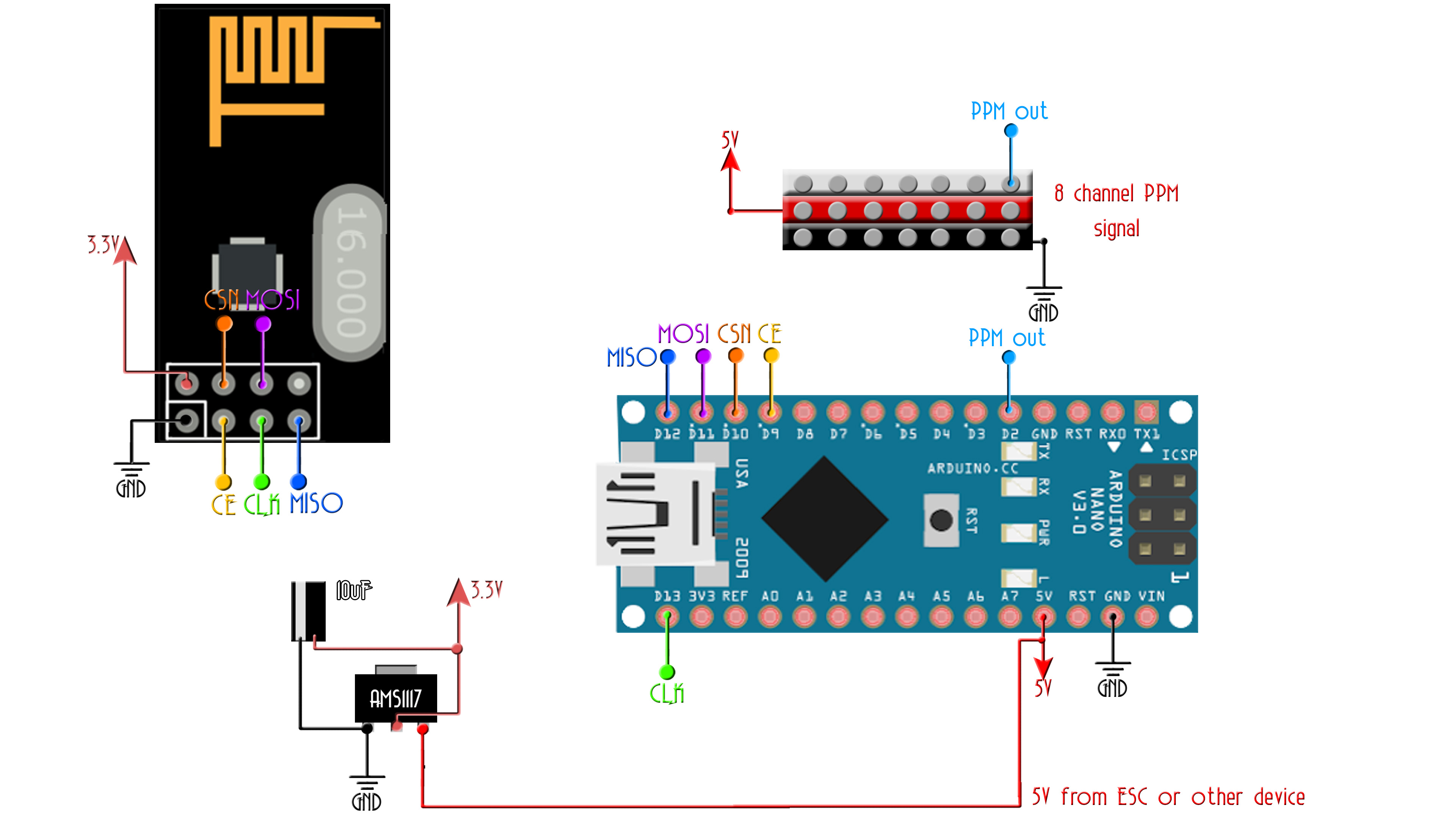
* Module // Arduino UNO,NANO
GND -> GND
Vcc -> 3.3V
CE -> D9
CSN -> D10
CLK -> D13
MOSI -> D11
MISO -> D12
A basic receiver test for the nRF24L01 module to receive 6 channels send a ppm sum
with all of them on digital pin D2. Install NRF24 library before you compile
Please, like, share and subscribe on my https://www.youtube.com/c/ELECTRONOOBS
*/
#include <SPI.h>
#include <nRF24L01.h> //Downlaod here: https://www.electronoobs.com/eng_arduino_NRF24_lib.php
#include <RF24.h>
////////////////////// PPM CONFIGURATION//////////////////////////
#define channel_number 6 //set the number of channels
#define sigPin 2 //set PPM signal output pin on the arduino
#define PPM_FrLen 27000 //set the PPM frame length in microseconds (1ms = 1000µs)
#define PPM_PulseLen 400 //set the pulse length
//////////////////////////////////////////////////////////////////
int ppm[channel_number];
const uint64_t pipeIn = 0xE8E8F0F0E1LL;
RF24 radio(7, 8);
// The sizeof this struct should not exceed 32 bytes
struct MyData {
byte throttle;
byte yaw;
byte pitch;
byte roll;
byte AUX1;
byte AUX2;
};
MyData data;
void resetData()
{
// 'safe' values to use when no radio input is detected
data.throttle = 0;
data.yaw = 127;
data.pitch = 127;
data.roll = 127;
data.AUX1 = 0;
data.AUX2= 0;
setPPMValuesFromData();
}
void setPPMValuesFromData()
{
ppm[0] = map(data.throttle, 0, 255, 1000, 2000);
ppm[1] = map(data.yaw, 0, 255, 1000, 2000);
ppm[2] = map(data.pitch, 0, 255, 1000, 2000);
ppm[3] = map(data.roll, 0, 255, 1000, 2000);
ppm[4] = map(data.AUX1, 0, 1, 1000, 2000);
ppm[5] = map(data.AUX2, 0, 1, 1000, 2000);
}
/**************************************************/
void setupPPM() {
pinMode(sigPin, OUTPUT);
digitalWrite(sigPin, 0); //set the PPM signal pin to the default state (off)
cli();
TCCR1A = 0; // set entire TCCR1 register to 0
TCCR1B = 0;
OCR1A = 100; // compare match register (not very important, sets the timeout for the first interrupt)
TCCR1B |= (1 << WGM12); // turn on CTC mode
TCCR1B |= (1 << CS11); // 8 prescaler: 0,5 microseconds at 16mhz
TIMSK1 |= (1 << OCIE1A); // enable timer compare interrupt
sei();
}
void setup()
{
resetData();
setupPPM();
// Set up radio module
radio.begin();
radio.setDataRate(RF24_250KBPS); // Both endpoints must have this set the same
radio.setAutoAck(false);
radio.openReadingPipe(1,pipeIn);
radio.startListening();
}
/**************************************************/
unsigned long lastRecvTime = 0;
void recvData()
{
while ( radio.available() ) {
radio.read(&data, sizeof(MyData));
lastRecvTime = millis();
}
}
/**************************************************/
void loop()
{
recvData();
unsigned long now = millis();
if ( now - lastRecvTime > 1000 ) {
// signal lost?
resetData();
}
setPPMValuesFromData();
}
/**************************************************/
//#error Delete this line befor you cahnge the value (clockMultiplier) below
#define clockMultiplier 2 // set this to 2 if you are using a 16MHz arduino, leave as 1 for an 8MHz arduino
ISR(TIMER1_COMPA_vect){
static boolean state = true;
TCNT1 = 0;
if ( state ) {
//end pulse
PORTD = PORTD & ~B00000100; // turn pin 2 off. Could also use: digitalWrite(sigPin,0)
OCR1A = PPM_PulseLen * clockMultiplier;
state = false;
}
else {
//start pulse
static byte cur_chan_numb;
static unsigned int calc_rest;
PORTD = PORTD | B00000100; // turn pin 2 on. Could also use: digitalWrite(sigPin,1)
state = true;
if(cur_chan_numb >= channel_number) {
cur_chan_numb = 0;
calc_rest += PPM_PulseLen;
OCR1A = (PPM_FrLen - calc_rest) * clockMultiplier;
calc_rest = 0;
}
else {
OCR1A = (ppm[cur_chan_numb] - PPM_PulseLen) * clockMultiplier;
calc_rest += ppm[cur_chan_numb];
cur_chan_numb++;
}
}
}