Original post here.
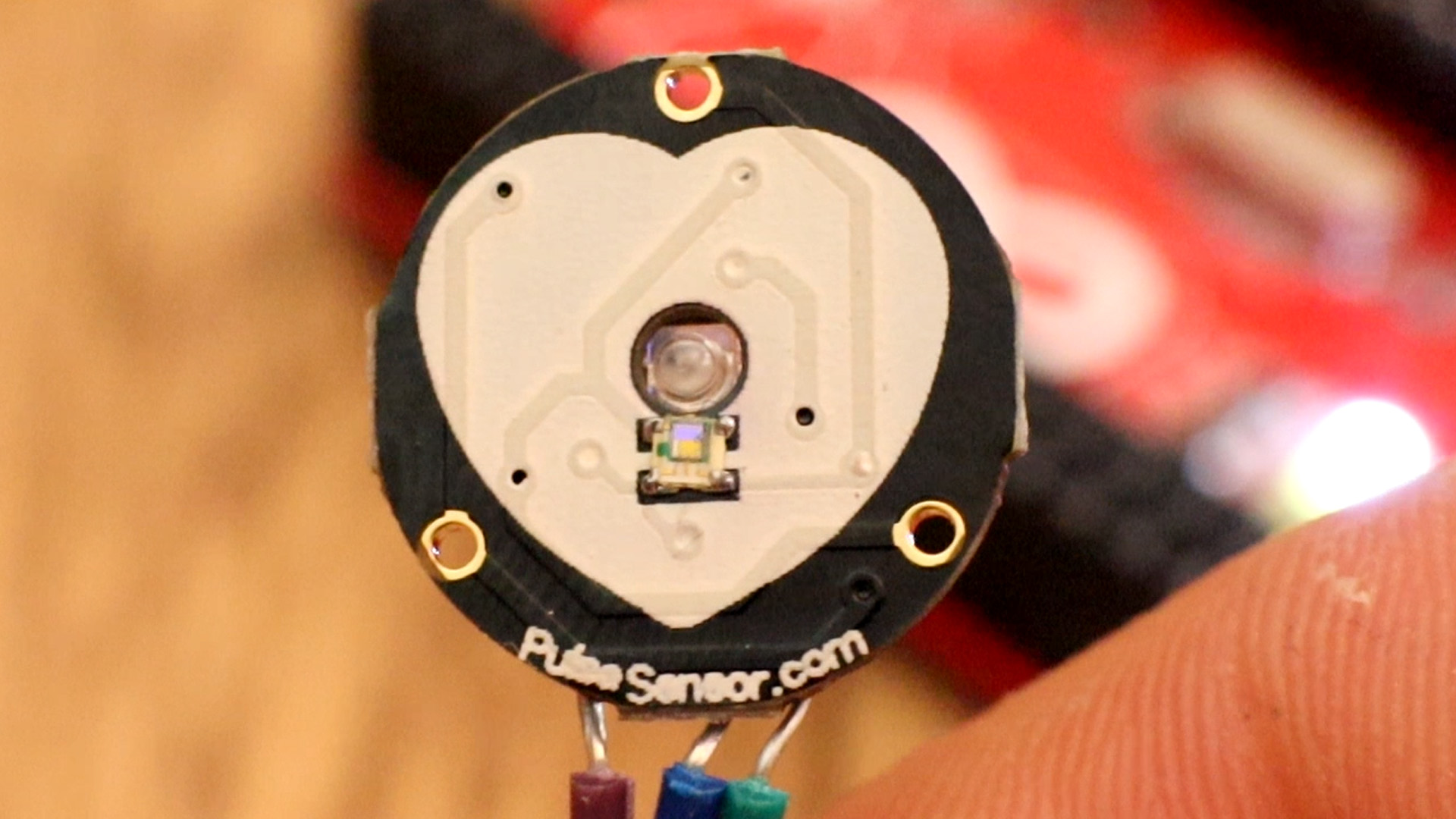
Heart Rate data can be used in many Electronic design and microcontroller projects. But the heart rate data is difficult to read, however the Pulse Sensor Amped help us to read heart rate. The Pulse Sensor Amped is a plug-and-play heart-rate sensor for Arduino. It can be used by students, artists, athletes, makers, and game & mobile developers who want to easily incorporate live heart-rate data into their projects.
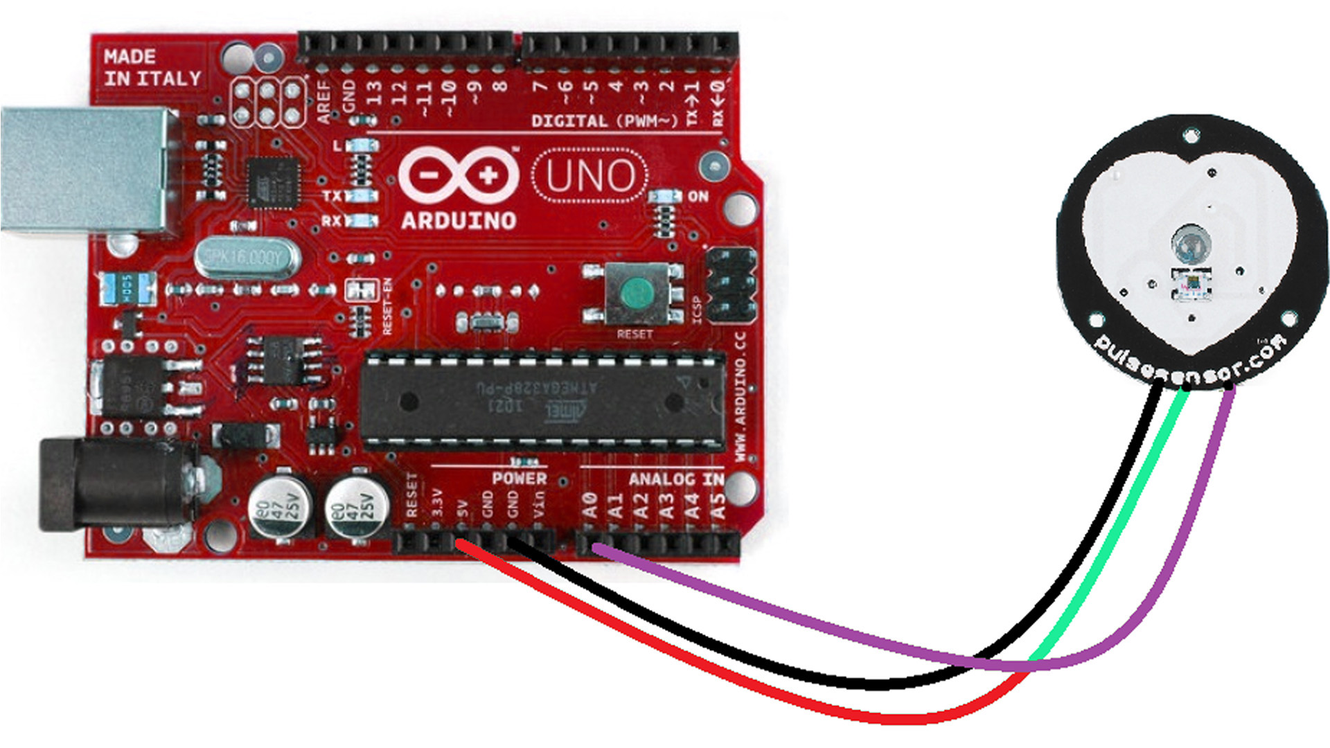
Connect the sensor’s power supply pins to the arduino board supply pin as Red – 5V, Black – GND and Purple – A0 (analog input 0) its over. This Analog input reading can be displayed in serial terminal of Arduino IDE or it can be drawn as pulse by using Processing IDE.
First of all make sure you have the interrupt.ino file is on the same folder as the pulse_sensor.ino file. If those files are not together, the code won't work. If you download the zip file below, you will have both codes in the same folder so that will work. If you don't downlaod the file, copy both codes below and put those in the same folder. Compile and uplaod and then we will see the Processing code.
/*>> Pulse Sensor Amped 1.2 <<
This code is for Pulse Sensor Amped by Joel Murphy and Yury Gitman
www.pulsesensor.com
>>> Pulse Sensor purple wire goes to Analog Pin 0 <<<
Pulse Sensor sample aquisition and processing happens in the background via Timer 2 interrupt. 2mS sample rate.
PWM on pins 3 and 11 will not work when using this code, because we are using Timer 2!
The following variables are automatically updated:
Signal : int that holds the analog signal data straight from the sensor. updated every 2mS.
IBI : int that holds the time interval between beats. 2mS resolution.
BPM : int that holds the heart rate value, derived every beat, from averaging previous 10 IBI values.
QS : boolean that is made true whenever Pulse is found and BPM is updated. User must reset.
Pulse : boolean that is true when a heartbeat is sensed then false in time with pin13 LED going out.
This code is designed with output serial data to Processing sketch "PulseSensorAmped_Processing-xx"
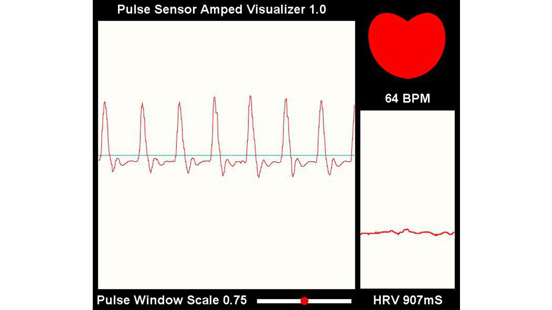
The Processing sketch is a simple data visualizer.
All the work to find the heartbeat and determine the heartrate happens in the code below.
Pin 13 LED will blink with heartbeat.
If you want to use pin 13 for something else, adjust the interrupt handler
It will also fade an LED on pin fadePin with every beat. Put an LED and series resistor from fadePin to GND.
Check here for detailed code walkthrough:
http://pulsesensor.myshopify.com/pages/pulse-sensor-amped-arduino-v1dot1
Code Version 1.2 by Joel Murphy & Yury Gitman Spring 2013
This update fixes the firstBeat and secondBeat flag usage so that realistic BPM is reported.
*/
// VARIABLES
int pulsePin = 0; // Pulse Sensor purple wire connected to analog pin 0
int blinkPin = 13; // pin to blink led at each beat
int fadePin = 5; // pin to do fancy classy fading blink at each beat
int fadeRate = 0; // used to fade LED on with PWM on fadePin
// these variables are volatile because they are used during the interrupt service routine!
volatile int BPM; // used to hold the pulse rate
volatile int Signal; // holds the incoming raw data
volatile int IBI = 600; // holds the time between beats, must be seeded!
volatile boolean Pulse = false; // true when pulse wave is high, false when it's low
volatile boolean QS = false; // becomes true when Arduoino finds a beat.
void setup(){
pinMode(blinkPin,OUTPUT); // pin that will blink to your heartbeat!
pinMode(fadePin,OUTPUT); // pin that will fade to your heartbeat!
Serial.begin(115200); // we agree to talk fast!
interruptSetup(); // sets up to read Pulse Sensor signal every 2mS
// UN-COMMENT THE NEXT LINE IF YOU ARE POWERING The Pulse Sensor AT LOW VOLTAGE,
// AND APPLY THAT VOLTAGE TO THE A-REF PIN
//analogReference(EXTERNAL);
}
void loop(){
sendDataToProcessing('S', Signal); // send Processing the raw Pulse Sensor data
if (QS == true){ // Quantified Self flag is true when arduino finds a heartbeat
fadeRate = 255; // Set 'fadeRate' Variable to 255 to fade LED with pulse
sendDataToProcessing('B',BPM); // send heart rate with a 'B' prefix
sendDataToProcessing('Q',IBI); // send time between beats with a 'Q' prefix
QS = false; // reset the Quantified Self flag for next time
}
ledFadeToBeat();
delay(20); // take a break
}
void ledFadeToBeat(){
fadeRate -= 15; // set LED fade value
fadeRate = constrain(fadeRate,0,255); // keep LED fade value from going into negative numbers!
analogWrite(fadePin,fadeRate); // fade LED
}
void sendDataToProcessing(char symbol, int data ){
Serial.print(symbol); // symbol prefix tells Processing what type of data is coming
Serial.println(data); // the data to send culminating in a carriage return
}
volatile int rate[10];                    // array to hold last ten IBI values
volatile unsigned long sampleCounter = 0;          // used to determine pulse timing
volatile unsigned long lastBeatTime = 0;           // used to find IBI
volatile int P =512;                      // used to find peak in pulse wave, seeded
volatile int T = 512;                     // used to find trough in pulse wave, seeded
volatile int thresh = 512;                // used to find instant moment of heart beat, seeded
volatile int amp = 100;                   // used to hold amplitude of pulse waveform, seeded
volatile boolean firstBeat = true;        // used to seed rate array so we startup with reasonable BPM
volatile boolean secondBeat = false;      // used to seed rate array so we startup with reasonable BPM


void interruptSetup(){
  // Initializes Timer2 to throw an interrupt every 2mS.
  TCCR2A = 0x02;     // DISABLE PWM ON DIGITAL PINS 3 AND 11, AND GO INTO CTC MODE
  TCCR2B = 0x06;     // DON'T FORCE COMPARE, 256 PRESCALER
  OCR2A = 0X7C;      // SET THE TOP OF THE COUNT TO 124 FOR 500Hz SAMPLE RATE
  TIMSK2 = 0x02;     // ENABLE INTERRUPT ON MATCH BETWEEN TIMER2 AND OCR2A
  sei();             // MAKE SURE GLOBAL INTERRUPTS ARE ENABLED
}


// THIS IS THE TIMER 2 INTERRUPT SERVICE ROUTINE.
// Timer 2 makes sure that we take a reading every 2 miliseconds
ISR(TIMER2_COMPA_vect){                         // triggered when Timer2 counts to 124
  cli();                                      // disable interrupts while we do this
  Signal = analogRead(pulsePin);              // read the Pulse Sensor
  sampleCounter += 2;                         // keep track of the time in mS with this variable
  int N = sampleCounter - lastBeatTime;       // monitor the time since the last beat to avoid noise

    //  find the peak and trough of the pulse wave
  if(Signal < thresh && N > (IBI/5)*3){       // avoid dichrotic noise by waiting 3/5 of last IBI
    if (Signal < T){                        // T is the trough
      T = Signal;                         // keep track of lowest point in pulse wave
    }
  }

  if(Signal > thresh && Signal > P){          // thresh condition helps avoid noise
    P = Signal;                             // P is the peak
  }                                        // keep track of highest point in pulse wave

  //  NOW IT'S TIME TO LOOK FOR THE HEART BEAT
  // signal surges up in value every time there is a pulse
  if (N > 250){                                   // avoid high frequency noise
    if ( (Signal > thresh) && (Pulse == false) && (N > (IBI/5)*3) ){
      Pulse = true;                               // set the Pulse flag when we think there is a pulse
      digitalWrite(blinkPin,HIGH);                // turn on pin 13 LED
      IBI = sampleCounter - lastBeatTime;         // measure time between beats in mS
      lastBeatTime = sampleCounter;               // keep track of time for next pulse

      if(secondBeat){                        // if this is the second beat, if secondBeat == TRUE
        secondBeat = false;                  // clear secondBeat flag
        for(int i=0; i<=9; i++){             // seed the running total to get a realisitic BPM at startup
          rate[i] = IBI;
        }
      }

      if(firstBeat){                         // if it's the first time we found a beat, if firstBeat == TRUE
        firstBeat = false;                   // clear firstBeat flag
        secondBeat = true;                   // set the second beat flag
        sei();                               // enable interrupts again
        return;                              // IBI value is unreliable so discard it
      }


      // keep a running total of the last 10 IBI values
      word runningTotal = 0;                  // clear the runningTotal variable

      for(int i=0; i<=8; i++){                // shift data in the rate array
        rate[i] = rate[i+1];                  // and drop the oldest IBI value
        runningTotal += rate[i];              // add up the 9 oldest IBI values
      }

      rate[9] = IBI;                          // add the latest IBI to the rate array
      runningTotal += rate[9];                // add the latest IBI to runningTotal
      runningTotal /= 10;                     // average the last 10 IBI values
      BPM = 60000/runningTotal;               // how many beats can fit into a minute? that's BPM!
      QS = true;                              // set Quantified Self flag
      // QS FLAG IS NOT CLEARED INSIDE THIS ISR
    }
  }

  if (Signal < thresh && Pulse == true){   // when the values are going down, the beat is over
    digitalWrite(blinkPin,LOW);            // turn off pin 13 LED
    Pulse = false;                         // reset the Pulse flag so we can do it again
    amp = P - T;                           // get amplitude of the pulse wave
    thresh = amp/2 + T;                    // set thresh at 50% of the amplitude
    P = thresh;                            // reset these for next time
    T = thresh;
  }

  if (N > 2500){                           // if 2.5 seconds go by without a beat
    thresh = 512;                          // set thresh default
    P = 512;                               // set P default
    T = 512;                               // set T default
    lastBeatTime = sampleCounter;          // bring the lastBeatTime up to date
    firstBeat = true;                      // set these to avoid noise
    secondBeat = false;                    // when we get the heartbeat back
  }

  sei();                                   // enable interrupts when youre done!
}// end isr
The arduino will sense the pulses and send the data to the Processing code using the serial communication. So first, download Processing platform and make sure it works on your PC. You might need to update JAVA. Downlaod or copy the processing code and run it. Select the com of your Arduino and run the code.
/*
THIS PROGRAM WORKS WITH PulseSensorAmped_Arduino-xx ARDUINO CODE
THE PULSE DATA WINDOW IS SCALEABLE WITH SCROLLBAR AT BOTTOM OF SCREEN
PRESS 'S' OR 's' KEY TO SAVE A PICTURE OF THE SCREEN IN SKETCH FOLDER (.jpg)
MADE BY JOEL MURPHY AUGUST, 2012
*/


import processing.serial.*;
PFont font;
Scrollbar scaleBar;

Serial port;

int Sensor;      // HOLDS PULSE SENSOR DATA FROM ARDUINO
int IBI;         // HOLDS TIME BETWEN HEARTBEATS FROM ARDUINO
int BPM;         // HOLDS HEART RATE VALUE FROM ARDUINO
int[] RawY;      // HOLDS HEARTBEAT WAVEFORM DATA BEFORE SCALING
int[] ScaledY;   // USED TO POSITION SCALED HEARTBEAT WAVEFORM
int[] rate;      // USED TO POSITION BPM DATA WAVEFORM
float zoom;      // USED WHEN SCALING PULSE WAVEFORM TO PULSE WINDOW
float offset;    // USED WHEN SCALING PULSE WAVEFORM TO PULSE WINDOW
color eggshell = color(255, 253, 248);
int heart = 0;   // This variable times the heart image 'pulse' on screen
//  THESE VARIABLES DETERMINE THE SIZE OF THE DATA WINDOWS
int PulseWindowWidth = 490;
int PulseWindowHeight = 512;
int BPMWindowWidth = 180;
int BPMWindowHeight = 340;
boolean beat = false;    // set when a heart beat is detected, then cleared when the BPM graph is advanced


void setup() {
  size(700, 600);  // Stage size
  frameRate(100);
  font = loadFont("Arial-BoldMT-24.vlw");
  textFont(font);
  textAlign(CENTER);
  rectMode(CENTER);
  ellipseMode(CENTER);
// Scrollbar constructor inputs: x,y,width,height,minVal,maxVal
  scaleBar = new Scrollbar (400, 575, 180, 12, 0.5, 1.0);  // set parameters for the scale bar
  RawY = new int[PulseWindowWidth];          // initialize raw pulse waveform array
  ScaledY = new int[PulseWindowWidth];       // initialize scaled pulse waveform array
  rate = new int [BPMWindowWidth];           // initialize BPM waveform array
  zoom = 0.75;                               // initialize scale of heartbeat window

// set the visualizer lines to 0
 for (int i=0; i<rate.length; i++){
    rate[i] = 555;      // Place BPM graph line at bottom of BPM Window
   }
 for (int i=0; i<RawY.length; i++){
    RawY[i] = height/2; // initialize the pulse window data line to V/2
 }

// GO FIND THE ARDUINO
  println(Serial.list());    // print a list of available serial ports
  // choose the number between the [] that is connected to the Arduino
  port = new Serial(this, Serial.list()[0], 115200);  // make sure Arduino is talking serial at this baud rate
  port.clear();            // flush buffer
  port.bufferUntil('\n');  // set buffer full flag on receipt of carriage return
}

void draw() {
  background(0);
  noStroke();
// DRAW OUT THE PULSE WINDOW AND BPM WINDOW RECTANGLES
  fill(eggshell);  // color for the window background
  rect(255,height/2,PulseWindowWidth,PulseWindowHeight);
  rect(600,385,BPMWindowWidth,BPMWindowHeight);

// DRAW THE PULSE WAVEFORM
  // prepare pulse data points
  RawY[RawY.length-1] = (1023 - Sensor) - 212;   // place the new raw datapoint at the end of the array
  zoom = scaleBar.getPos();                      // get current waveform scale value
  offset = map(zoom,0.5,1,150,0);                // calculate the offset needed at this scale
  for (int i = 0; i < RawY.length-1; i++) {      // move the pulse waveform by
    RawY[i] = RawY[i+1];                         // shifting all raw datapoints one pixel left
    float dummy = RawY[i] * zoom + offset;       // adjust the raw data to the selected scale
    ScaledY[i] = constrain(int(dummy),44,556);   // transfer the raw data array to the scaled array
  }
  stroke(250,0,0);                               // red is a good color for the pulse waveform
  noFill();
  beginShape();                                  // using beginShape() renders fast
  for (int x = 1; x < ScaledY.length-1; x++) {
    vertex(x+10, ScaledY[x]);                    //draw a line connecting the data points
  }
  endShape();

// DRAW THE BPM WAVE FORM
// first, shift the BPM waveform over to fit then next data point only when a beat is found
 if (beat == true){   // move the heart rate line over one pixel every time the heart beats
   beat = false;      // clear beat flag (beat flag waset in serialEvent tab)
   for (int i=0; i<rate.length-1; i++){
     rate[i] = rate[i+1];                  // shift the bpm Y coordinates over one pixel to the left
   }
// then limit and scale the BPM value
   BPM = min(BPM,200);                     // limit the highest BPM value to 200
   float dummy = map(BPM,0,200,555,215);   // map it to the heart rate window Y
   rate[rate.length-1] = int(dummy);       // set the rightmost pixel to the new data point value
 }
 // GRAPH THE HEART RATE WAVEFORM
 stroke(250,0,0);                          // color of heart rate graph
 strokeWeight(2);                          // thicker line is easier to read
 noFill();
 beginShape();
 for (int i=0; i < rate.length-1; i++){    // variable 'i' will take the place of pixel x position
   vertex(i+510, rate[i]);                 // display history of heart rate datapoints
 }
 endShape();

// DRAW THE HEART AND MAYBE MAKE IT BEAT
  fill(250,0,0);
  stroke(250,0,0);
  // the 'heart' variable is set in serialEvent when arduino sees a beat happen
  heart--;                    // heart is used to time how long the heart graphic swells when your heart beats
  heart = max(heart,0);       // don't let the heart variable go into negative numbers
  if (heart > 0){             // if a beat happened recently,
    strokeWeight(8);          // make the heart big
  }
  smooth();   // draw the heart with two bezier curves
  bezier(width-100,50, width-20,-20, width,140, width-100,150);
  bezier(width-100,50, width-190,-20, width-200,140, width-100,150);
  strokeWeight(1);          // reset the strokeWeight for next time


// PRINT THE DATA AND VARIABLE VALUES
  fill(eggshell);                                       // get ready to print text
  text("Pulse Sensor Amped Visualizer 1.1",245,30);     // tell them what you are
  text("IBI " + IBI + "mS",600,585);                    // print the time between heartbeats in mS
  text(BPM + " BPM",600,200);                           // print the Beats Per Minute
  text("Pulse Window Scale " + nf(zoom,1,2), 150, 585); // show the current scale of Pulse Window

//  DO THE SCROLLBAR THINGS
  scaleBar.update (mouseX, mouseY);
  scaleBar.display();

//
}  //end of draw loop
}// end isr