


I just found this NEXTION display on the internet and after a few tests, I've learned how to use it and in this tutorial I will show you how to do that as well with a few examples of pushing buttons, changing screens, geting data to the Arduino and from the Arduino and a wave example. In this tutorial you will find the schematic you need, the steps to crate the TFT file and how to uplaod it to the screen and also the exampel code for the Arduino. Let's start!
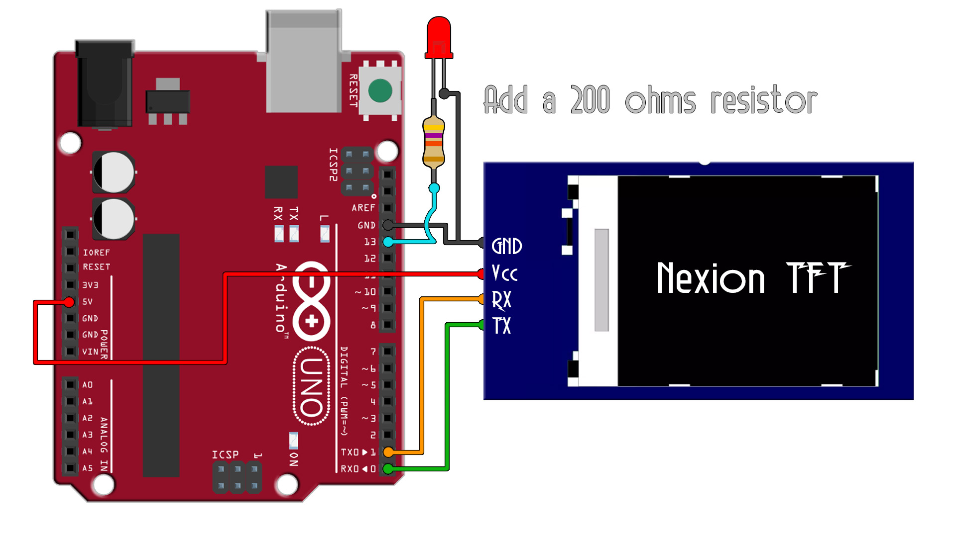
Ok, first of all, for this first example we need the schematic below. But only make the connections after we uplaod the code since the display uses the RX and TX pins and if something is connected to those pins, we can't uplaod the code. But we need the Arduino code part but also the Nextion TFT interface. For that we will use Nextion editor and create our interface.
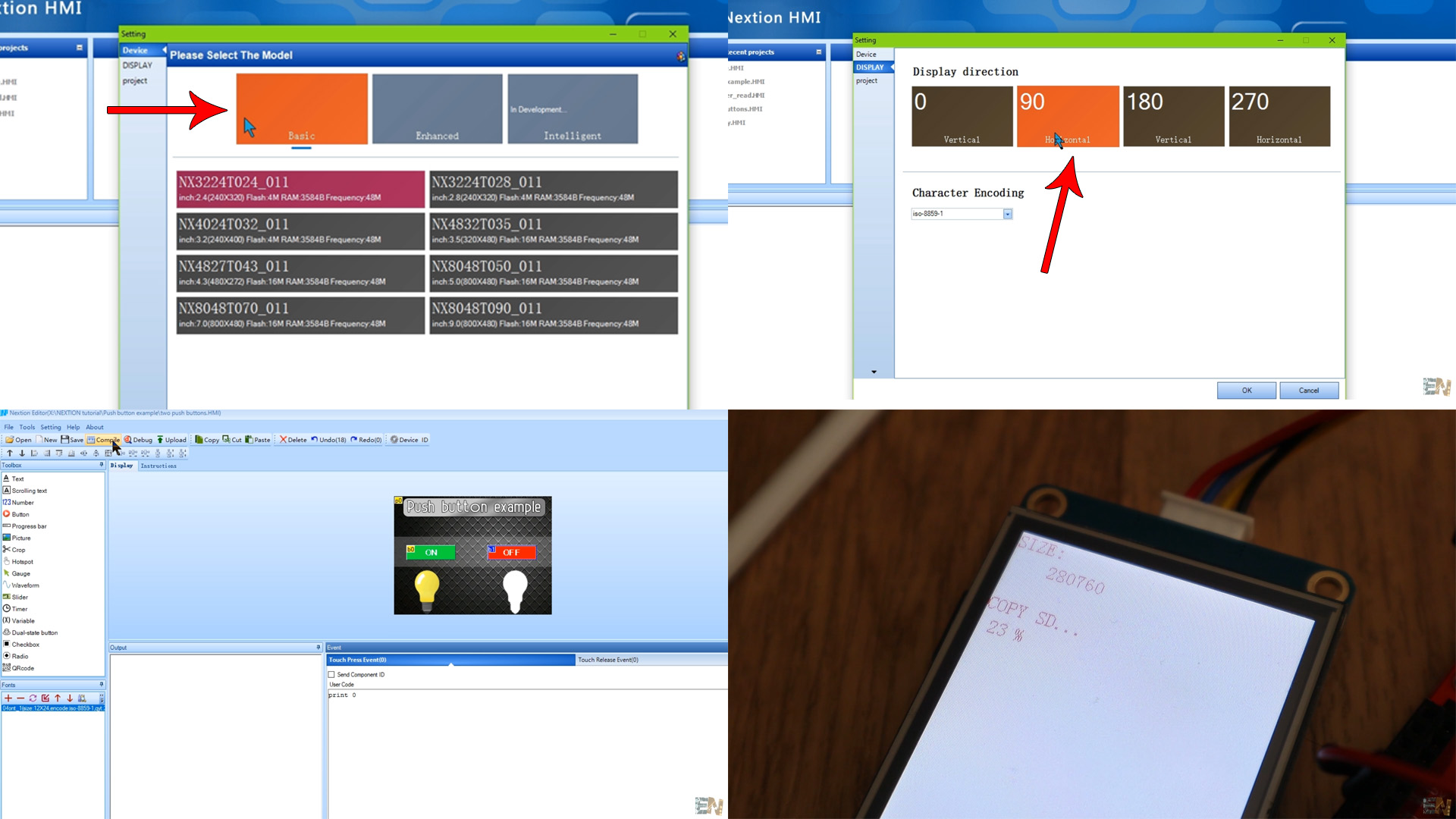
Downlaod from below the Nextion editor software and install it. Then run the aplication and create a new file. In the first window select the type of TFT display you use and in my cse, I select the horizontal screen. Then I add a background image that I've made in Photoshop of 240 by 240 pixels as my screen is. I then add two button from the toolbar on the left side. On the bottom corner we have the configuration of the selected variable.
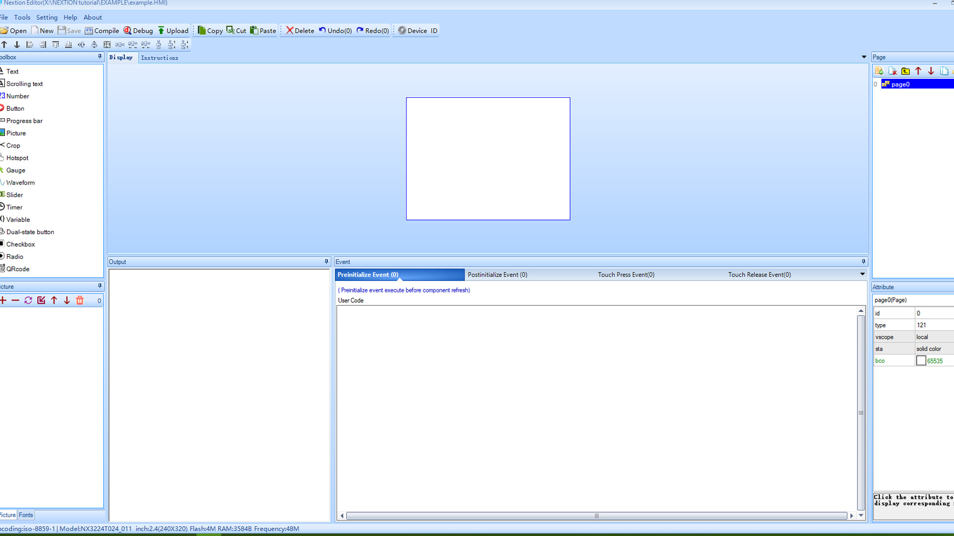
Below you have the layout of the NEXTION editor. We haev the toolbar on the left side. Here we haev all the tools such as buttons, weves, etc. Below this we have the images and fonts. On the right side we have the selected screen and below that the settings of the selected variable. In the middle and bottom side we have the console and the event tab for each selected varaiable.
Go to tools and there create a new font, otherwise you won't be ablle to print text. Once you make the font, sabe the file and in the bottom left corner you will have a new font with the 0 number. Then go to the button variable you ahve place don the screeen adn select font "0".
Ok, so I've placed 2 buttons and in the Event tab, I put a print 0 when the OFF button is pressed and a print 1 when the ON is pressed. After we connect to the ARduino, we will receive a 1 each time we press the ON and a 0 each time we press the OFF. To uplaod the TFT file we have to compile the project. If we have no errors in the console, we go to File and select open build folder anc copy the tft file. Insert a micro SD card into your PC and copy the tft file there. The SD card must be empty and formated to a fat32 format.
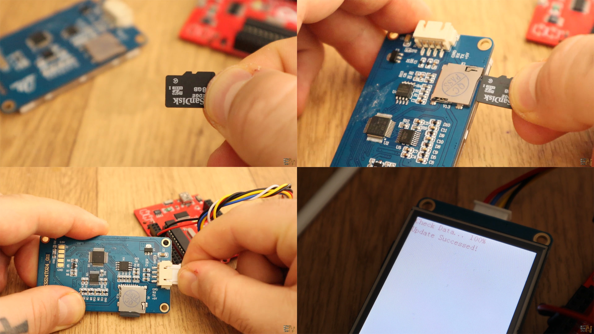
Now that the tft file is on the SD card make sure the Nextion display is not powered on. Insert the SC dard into the card slot. Now power up the display with 5V. You will see on the screen that the new tft interface is being uploaded. Once you see 100%, power off the display and remove the SD card. Now power back the display and connect the TX and RX pins as in the schematic and add a LED to pin 13.
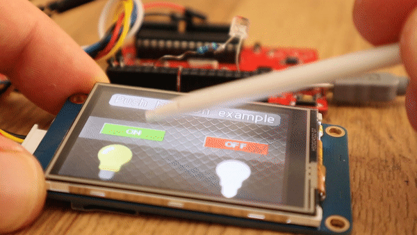
Copy the code from below or just download it. Upload the code to the arduino before you connect the TX and RX pins. After you uplaod the code, connect the UART TX and RX pins and power up the Arduino and display. Connect the LED and start touching the screen as you can see in the video below.
int LED = 13;                               //Define the pin for the LED

void setup() {
  Serial.begin(9600);                       //The default baud rate of the Nextion TFT is 9600.
  pinMode(LED,OUTPUT);                      //Define pin as OUTPUT

}

void loop() {
  if(Serial.available()>0)                  //If we receive something...
  {
    String Received = Serial.readString();  //Save the received String in the Received variable
    if(int(Received[0]) == 1)               //If the first character of "Received" is "1"
    {
      digitalWrite(LED,HIGH);               //We turn on the LED
    }
    if(int(Received[0]) == 0)               //if is a "0"
    {
      digitalWrite(LED,LOW);                //We turn the LED off
    }
  }

}


