A few weeks ago we had the first version of this project, the portable soldering iron V1.0 and that had a few problems. The main problem was the soldering tip that I've used. It was very low quality but I wanted that tip because it had the thermocouple and heating element with separated wires. But now, I've got a much better tip, the T12. This one has the thermocouple and heating element in series so the circuit is different and the temperature s
by: ELECTRONOOBS on 2026-05-30
1 x PCB: LINK for GERBER
1 x ATMega328-AU: LINK eBay
1 x 16MHz crystal: LINK eBay
2 x 0802 22pF: LINK eBay
1 x T12 tip: LINK eBay
1 x buck converter: LINK eBay
1 x LM258: LINK eBay
1 x DC connector: LINK eBay
1 x vibrate sensor: LINK eBay
3 x PCB clip: LINK eBay
1 x IRF540N: LINK eBay
1 x OLED display: LINK eBay
1 x 2SC3356: LINK eBay
2 x 1N5819 diode: LINK eBay
2 x 90 degree push buttons: LINK eBay
1 x smd buzzer: LINK eBay
0805 resistors: LINK eBay
0603 resistors: LINK eBay
0805 capacitors: LINK eBay
0603 capacitors: LINK eBay
1 x FTDI programmer: LINK eBay
Wires LINK eBay
Wire, soldering iron, solder, etc...
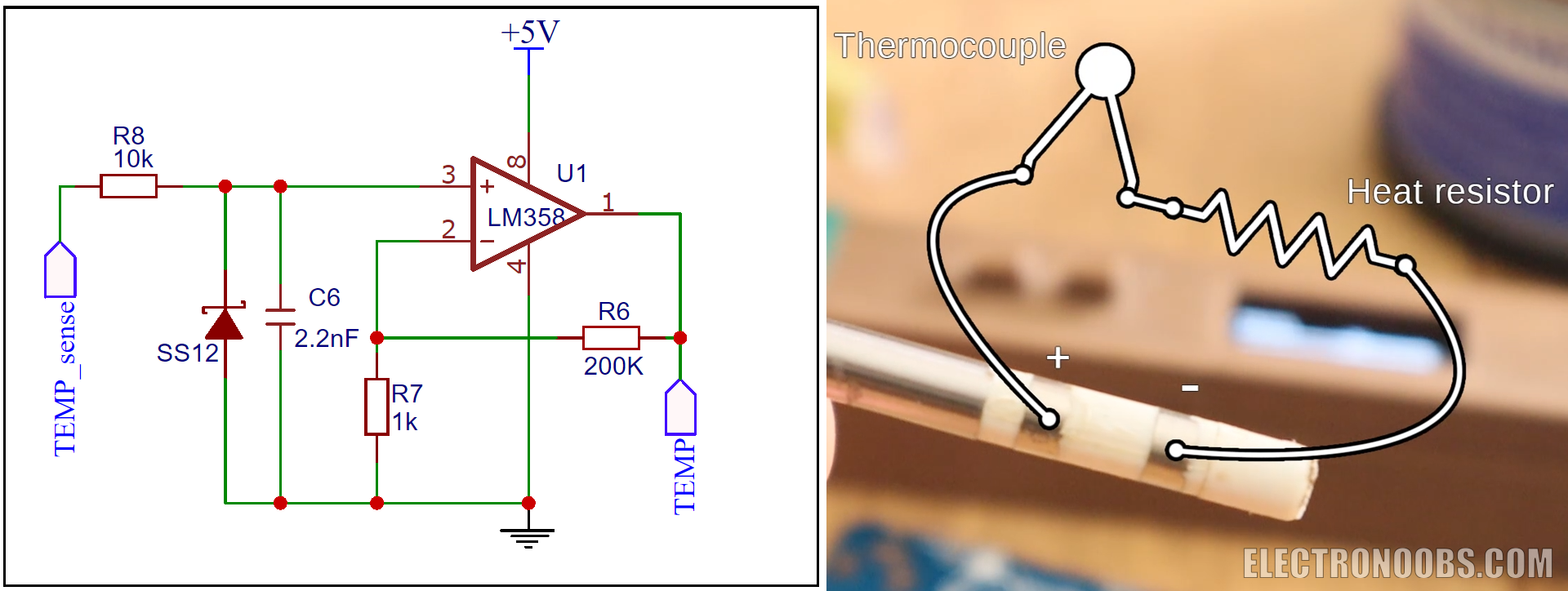
First, let's see what improvements we have for this new board. First, the Iron tip is not that big and ugly one anymore. Now we use the T12 tip. For taht the board has 3 PCB clips to fit the tip in place. The first clip is connected to nothing. But the two clips in the midle are positive and negative connections of the iron tip. Those connections are the thermocouple and heating elenent in series. To read then temperature, we now use and OPAMP configuration and amplify the voltage drop across the iron tip connectors and then read the temperature corresponding to that drop.
We now have side 90 degrees push buttons and that will give us more space on the board and the buttons are now easier to push. The board alos has a buzzer for sound signals such as entering sleep mode. A very interesting component is the vibration sensor which is just a tube with metal connectors inside. We will use this to get out of sleep mode when movement is detected. The board is still using the ATMega328p-AU chip at 16MHz and the same buck converter for 5V from main input of up to 24V. Same DC connector, same MOSFET and same other small components.
First, let's see how to read the temperature since we don't have the MAX6675 thermocouple driver anymore. We how have to read the temperature using an operation amplifier. Below we haev the part of the schematic with the LM358 OPAMP. The TEMP_sense is connected to the positive pin of the iron tip. The other connector of then tip is GND. By that we can now amplifiy the small voltage drop that will be created on the thermocouple wiht the temperature. The amplified signal goes to one analog input of the ATMega chip. So now we can read the voltage drop on the thermocouple. But how we can get the temperature?
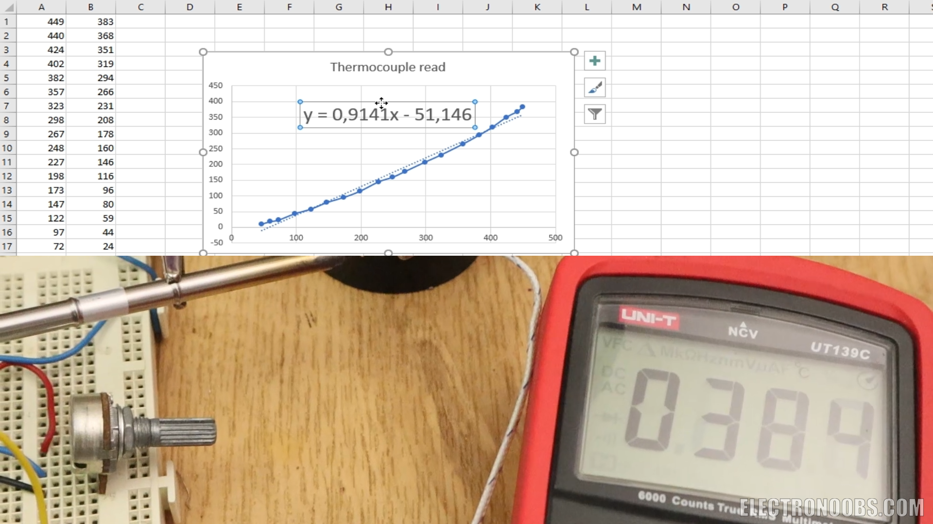
This is what I've done. I've conected the T12 tip to an external termocouple. Also to the OPAMP circuit and the output of that to and Arduino. I print the analog read to adn OLED screen and each 20 degrees or so I write down the measurement of the real temperature vs analog read. With that data I've amd a graph and get the lineal regression function. In the Arduino code, I'll use this function to get the temperature using the analog read.
As you can see in the bit of code below, I read the analog input, I then make the multisampling for more precision and then I get the temperature using the function before. The function then will return the temperature value.
float read_temperature()
{
   // Filter the ADC by multisampling with the values defined at the beginning
  int adc = 0;
  for (int i = 0; i < ADC_MULTISAMPLING_SAMPLES; ++i)
    adc += analogRead(temp_sense);
    adc = adc >> ADC_MULTISAMPLING;
  //Get the linear regression equations from excel data (Graph adc/temperature) (You need to perform real measures with externam thermometer)
  double temp =  0.9241*adc - 51.146;
  // Additional filtering
  CurrentTemp += (temp-CurrentTemp)*0.05;
  return(CurrentTemp);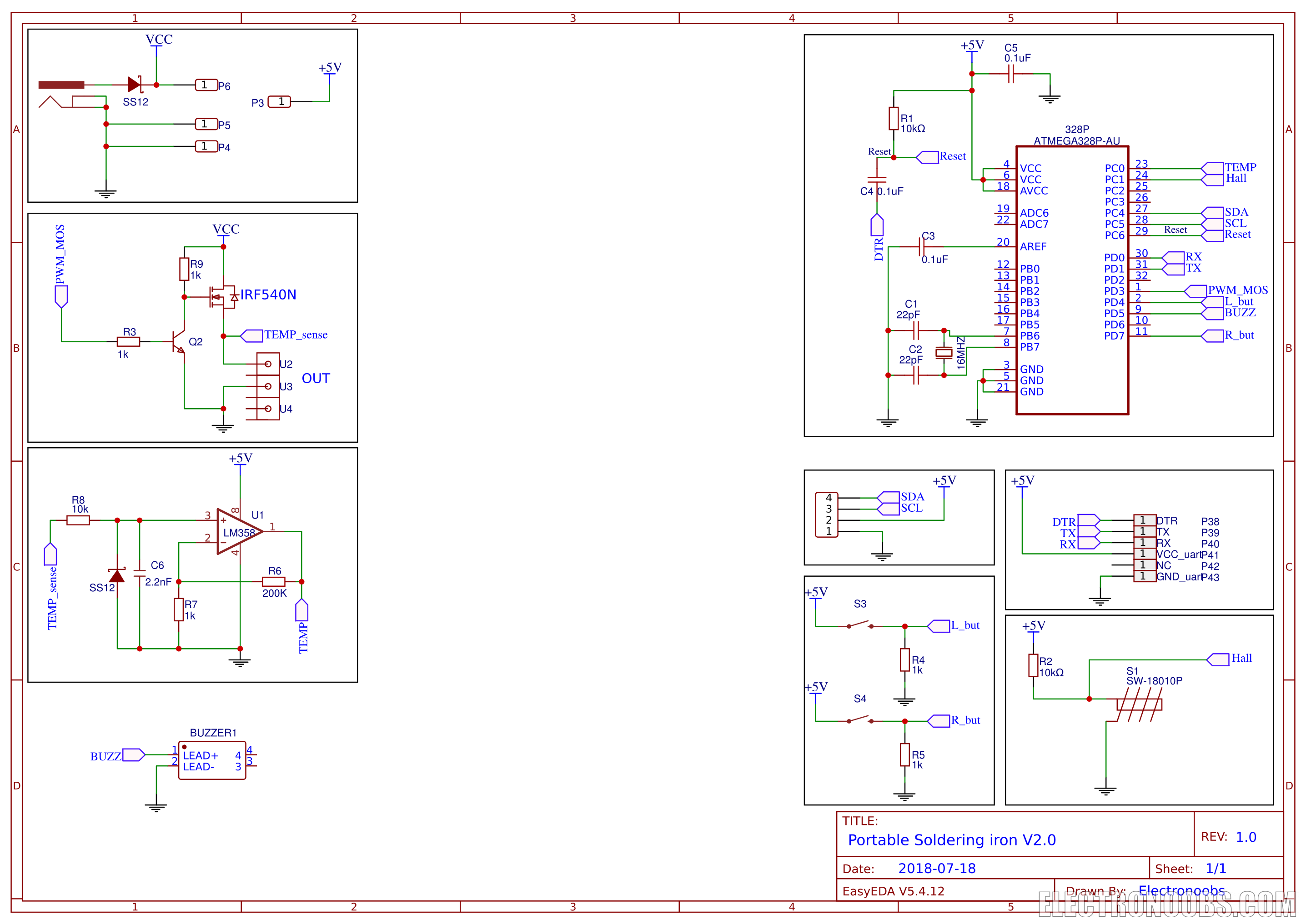
}Below you have the final schematic of this project. We haev 9 blocks. First is the main input plug and the buck copnverter for 5V. Then we haev the MOSFET circuit with a BJT as a driver at its gate and then connected to the iron tip. Thenwe haev the OPAMP circuit for temperature read. We can also see the buzzer, vibration sensor, the push buttons and of course, the ATMega328 chip.
Ok so we now have the board and everything soldered in place. The code is a bit long but don't worry. There are comments for each line so read the entire code to understand better. Lots of the lines are for the icons for the OLED display. Below you ahev the variables you could change if you want. These are the ones I've used. The "Delay" variable is for the loop time. Changing that time, the loop will be faster or slower. The "sleep_time_detect" is the time it takes to get into sleep mode in ms where 30000 is 5 minutes.
///////////////////////////////////////////////////////////////////////////////////////////////////////////////////////////////////////
//////////////////////////////////////////YOU COULD CHANGE THIS VALUES IF YOU NEED TO//////////////////////////////////////////////////
///////////////////////////////////////////////////////////////////////////////////////////////////////////////////////////////////////
//Editable Variables (change these values below to fit your project)
String Version = "Version 2.0";
float min_temp = 200;                            //This is the minimum temperature that the iron could get
float max_temp = 500;                            //This is the maximum temperature that the iron could get
float Delay=300;                                 //This is the time in ms the loop runs (PID+temperature read)
int   setpoint = 280;                            //Temperature setpoint initial value
unsigned long sleep_time_detect = 300000;        /*This is the time it has to wait with no vibrations till getting
                                                 into sleep mode. 300000 seconds = 5 minutes*/
///////////////////////////////////////////////////////////////////////////////////////////////////////////////////////////////////////
///////////////////////////////////////////////////////////////////////////////////////////////////////////////////////////////////////
///////////////////////////////////////////////////////////////////////////////////////////////////////////////////////////////////////For the code to work, remember you will need a few libraries such as the FAST PID, Adafruit_GFX and Adafruit_SSD1306. You could donwload those from below. You will get a .zip file. In Arduino IDE go to Sketch, include library, add .zip library and select the dowloaded file for each library and now you have those installed.
Comments


Leave a comment
Please login in order to comment.