


We will make a homemade ultrasonic distance sensor and see how these modules work. The working principle is quite simple but the circuit could get a bit tricky. We send a ultrasonic wave with the transmitter speaker, the wave hits an obstacle and bounce back to the receiver speaker. We calculate the time between the sent and received pulse, and by knowing the speed of sound which is constant, we can calculate the distance.
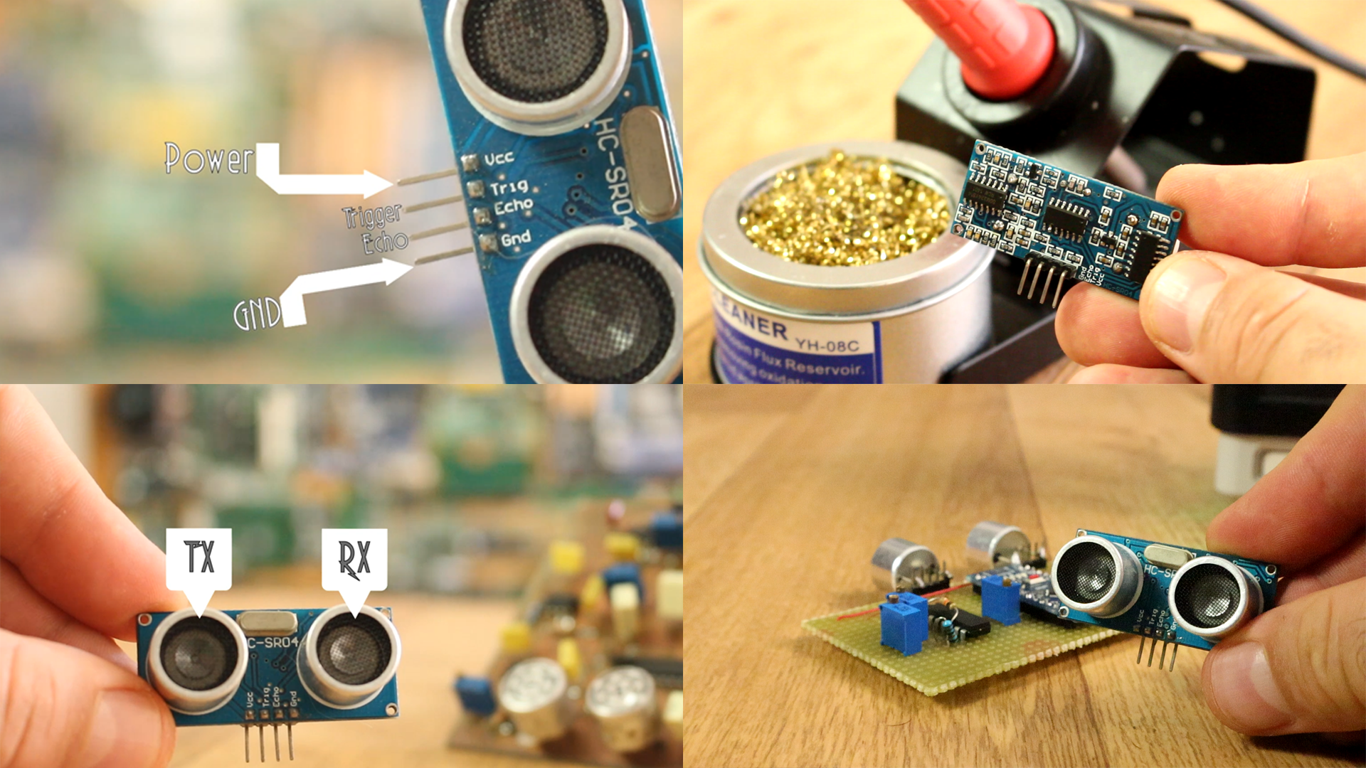
To begin this project, I first analyze this commercial ultrasonic distance sensor below, the SR04. What I can see is that it ahs 4 pins, ground, power, trigger pin and echo. It has some components on the back, and on the front part, the main components, two ultrasonic speakers. One as transmitter and the other one as receiver. Each time we apply a pulse to the trigger pin, the transmitter speaker creates a 40kHz sound wave.
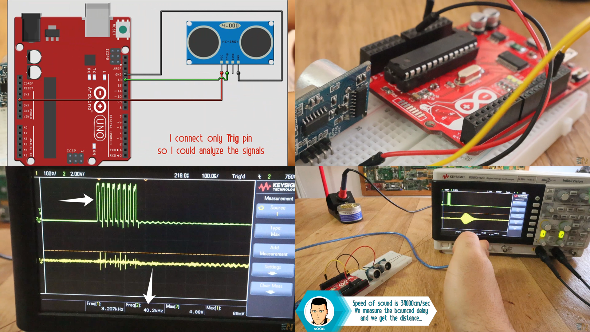
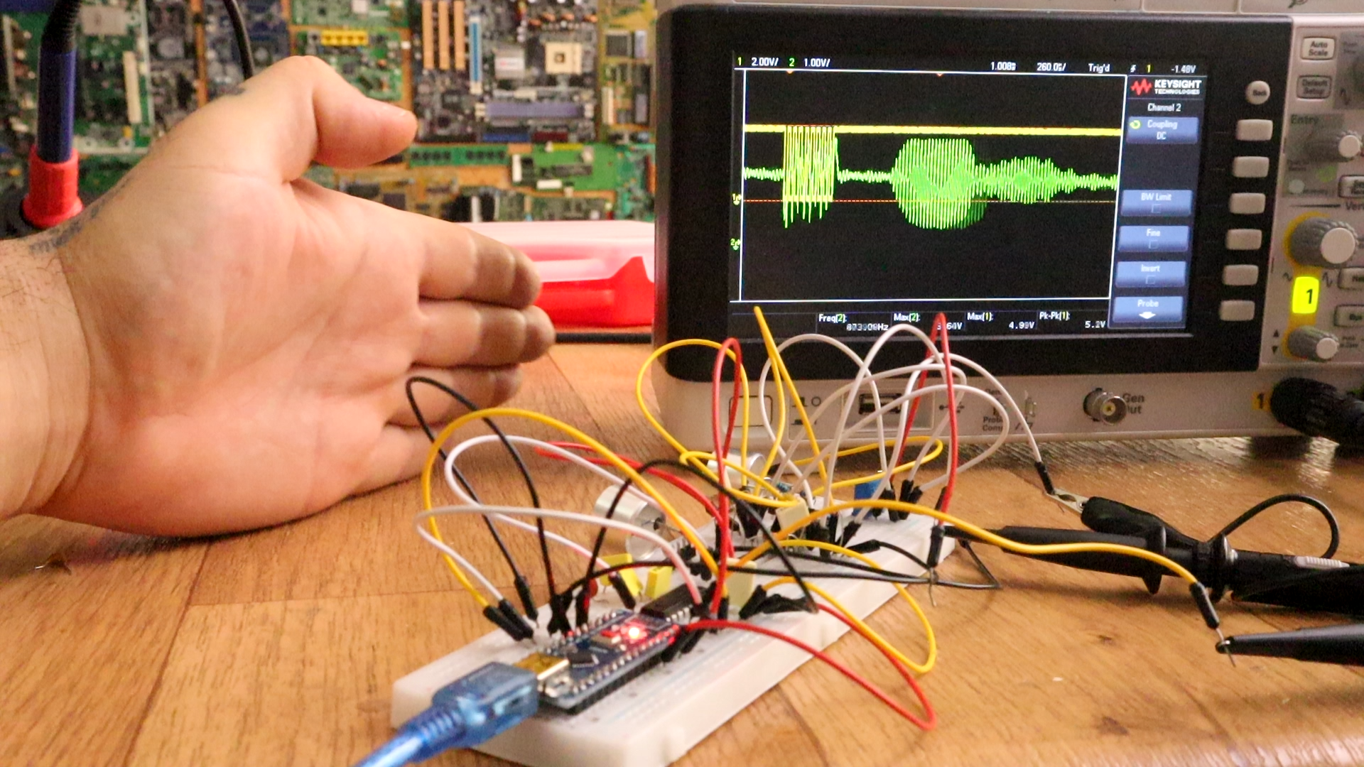
We have to analyze how it works and see the signals. For that, I've connected the trigger pin to and Arduino UNO and applied a 10us pulse each 100ms. I connect the TX and RX speakers to the oscilloscope and this is what I see. The green line is the TX signal. It is a 40KHz square wave applied to the transmitter speaker and that will send a sound wave burst. It has 8 cycles. Then, the yellow line is the received signal and it is the bounced sound wave. The time between the sent and received signal will give us information about the distance to the object.
As you can see below, there is a direct relation between the distance and the delay time between the sent and received pulse. That delay time is the tiem it took the sound wave to go to the object and get back. So we haev to divide that by 2. Then we multiply it by the speed of sound and we get the distance.
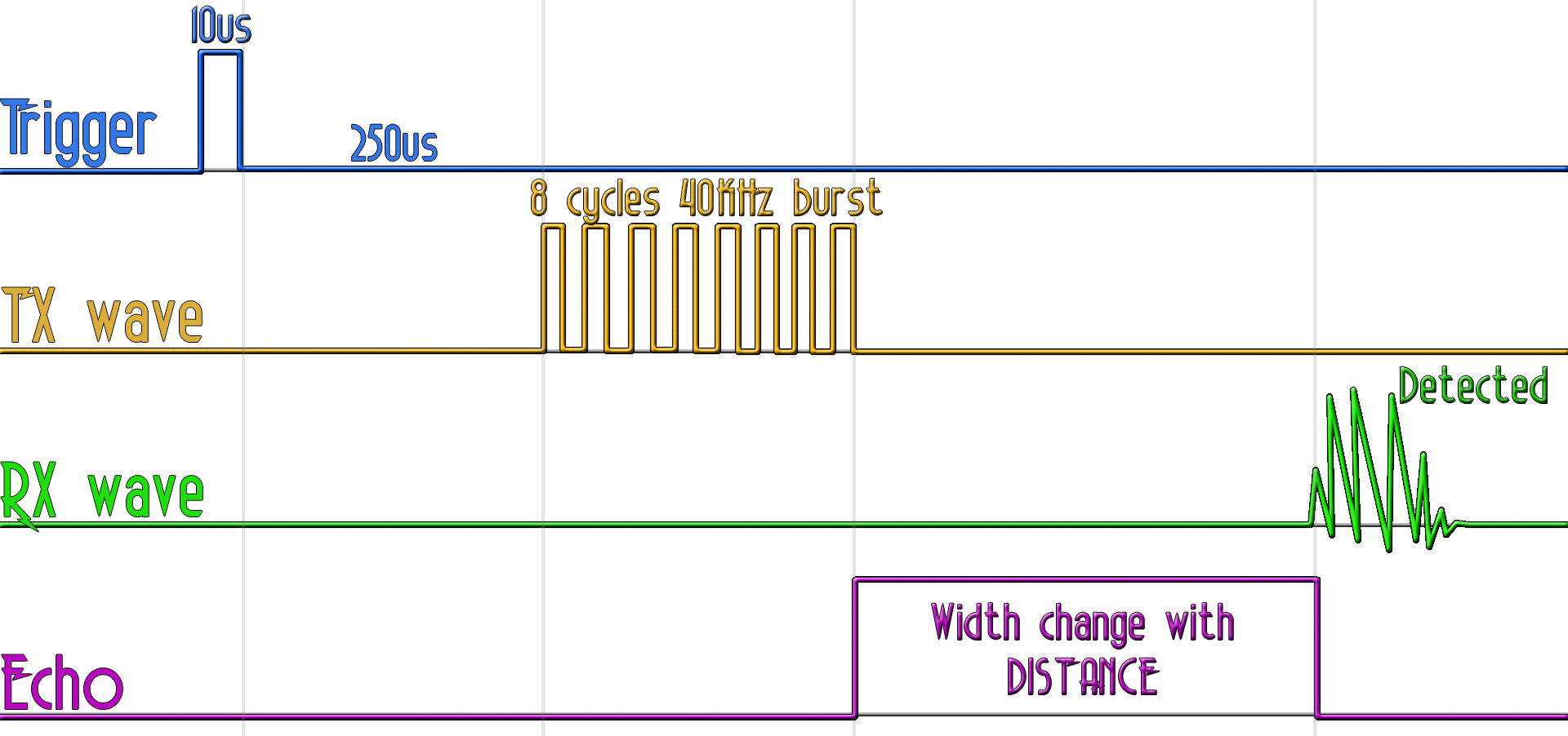
Ok, but the commercial module works like this. It receives the trigger signal. Waits 250us then it sends 8 cycles of 40KHz sound wave and puts the echo pin to high. That wave hits an object and bounce back. The receiver detects that sound and then it puts the echo pin to low. That creates a pulse and the width of that pulse is related to the measured distance. That's what we haev to implement today for our project.
First of all, this below, is the schematic that I've created for this project. You will need two ultrasonic speakers, one 1uad-OPAMP, the MAX232 voltage shifter the Arduino and a few more components such as PNP transistor, resistors and capacitors. I first mount this schematic on a breadboard for tests.

I have pins for trigger and echo just as the commercial module. Then the microcontroller connected to the lever shifter and it will apply 8 cycles of 40kHz signal after the trigger pulse, applied to the transmitter speaker. The good thing of using the MAX232 is that it has a voltage doubler and inverter. So I apply 5 V square signal to it and I can get over 30V peak to peak at the output that goes to the speaker and that will increase range. As you can see I send the square signal and receive that on the other speaker and it will change with the distance.
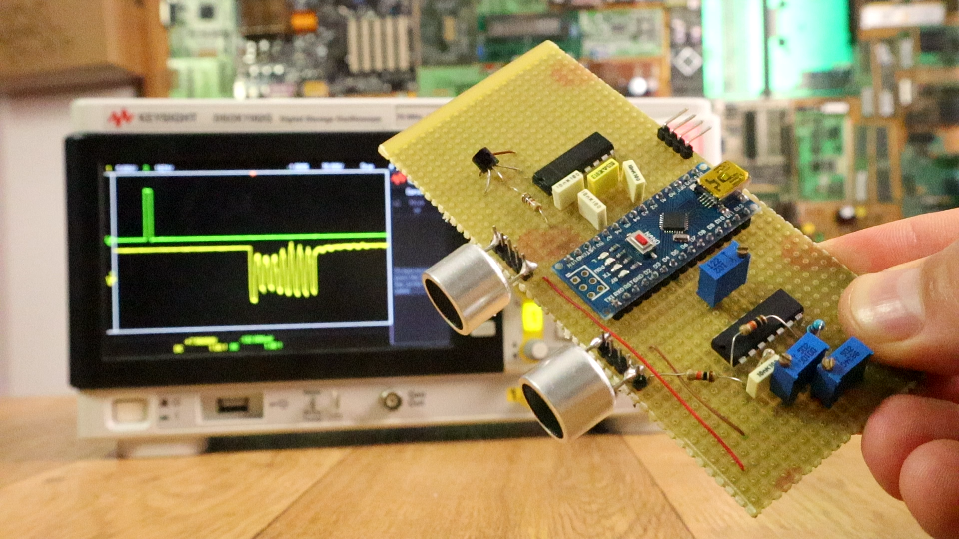
Now I mount everything on the PCB. Arduino in the middle and the amplified transmitter speaker on one side and the receiver on the other. We have potentiometers so we could set the treshold voltage for each amplified stage of the OPAMP se could get a good wave that will go to the Arduino. Now we haev to program the microcontroller.
The code is quite easy and short. First we set the registers for the ports so we define D3, D4, D5 and D10 as outputs. Those are TX out1, TX out2, Vcc activate and echo out pins. Then we set pin D9 and D8 to be able to fire an interruption.
We go to the interruption vector and if D8 is high, that means the trigger pin was activated so we can start the code. That will activate the loop in the infinite loop. We first have to add that delay of 250us we haev seen before. In the code that is 150us because after tests on the oscilloscope I saw a 100 extra delay so I've reduced the 250 delay to 150.
DDRD |= B00111000;  // Sets D3, D4, D5 outputs
DDRB |= B00000100;  // Sets D10 as output

PCICR  |= (1 << PCIE0);    //enable PCMSK0 scan
PCMSK0 |= (1 << PCINT0);  //Set pin D8 (trigger pin) set to fire interrupt on state change.
PCMSK0 |= (1 << PCINT1);  //Set pin D9 (echo in) set to fire an interrupt on state change.
Ok, after the delay we create 8 cycles of 40KHz on Tx out1 and Tx out 2 pins and that will send the 40KHz sound wave. But first we turn LOW the Vcc activate pin so the PNP connected to the MAX232 will be activated and the IC will be supplied. Then using a 12us delay, we create, more or less, a 40KHz signal. We do taht 8 times and then we put the Vcc activate back to high and we turn to HIGH the echo pin. Now when we detect the bounced signal we tutn echo pin to low and the pulse is over.
PORTD &= B11011111;   //D5 LOW    //Activate the MAX323 PNP transistor for supply

PORTD |= B00001000;   //D3 HIGH
PORTD &= B11101111;   //D4 LOW
delayMicroseconds(12);//12us so around 40KHz. Freq = 1/2*12us
PORTD &= B11110111;   //D3 LOW
PORTD |= B00010000;   //D4 HIGH
delayMicroseconds(12);
ISR(PCINT0_vect){
  //If digital D8 is high -> trigger was activated
  if(PINB & B00000001){
    Trig_in_state = true; //Set the Trig_in_state to true since we've detected the trigger pulse
  }
  //If trigger pin is low, the 10us pulse is over and we start the code
  else if(Trig_in_state)
  {
    triggered = true;     //Set trigered state to true
    Trig_in_state = false;    //Reset the D8 pin state
  }

  /*After the 8cycle burst each time there will be an interruption, that could be made by D8 or D9
  since those are the only 2 pins set as interrupt active
  So, since D8(trigger) is already low till next measurement, only D9 (echo in) could fire the interruption
  So, when we detect that, we set the echo out pin to low (D10) and end the echo pulse
  IMPORTANT: A better way to do this, is to also measure the echo in frequency to make sure
  it is around 40KHz, but I haven't done that. Works like this as well.
  */
  PORTB &= 11111011; //D10, echo pin out to LOW
}


