
What’s up my friends, welcome back. Today I’ve got a cool tutorial for you guys. So, I’ve seen these AMBILIGHT projects on the internet, so I had to make one myself. The process is very easy, but I thought I should show you how this works. You see, we will use addressable LED strip and control the brightness and color of each LED separately.
by: ELECTRONOOBS on 2026-07-24
One Arduino will read the color data from my computer screen using a USB connection and turn on and off the LEDs so it creates a background color the same as the screen. We will see how to control this kind of LEDs and how they work, how to connect the wires and how to setup the software for the colors, so let’s get started.
1 x Arduino NANO/UNO LINK eBay
1 x WS2812B OLED strip: LINK eBay
1 x USB cable: LINK eBay
1 x 5V-2A power supply: LINK eBay
Wires LINK eBay
Wire, soldering iron, solder, etc...
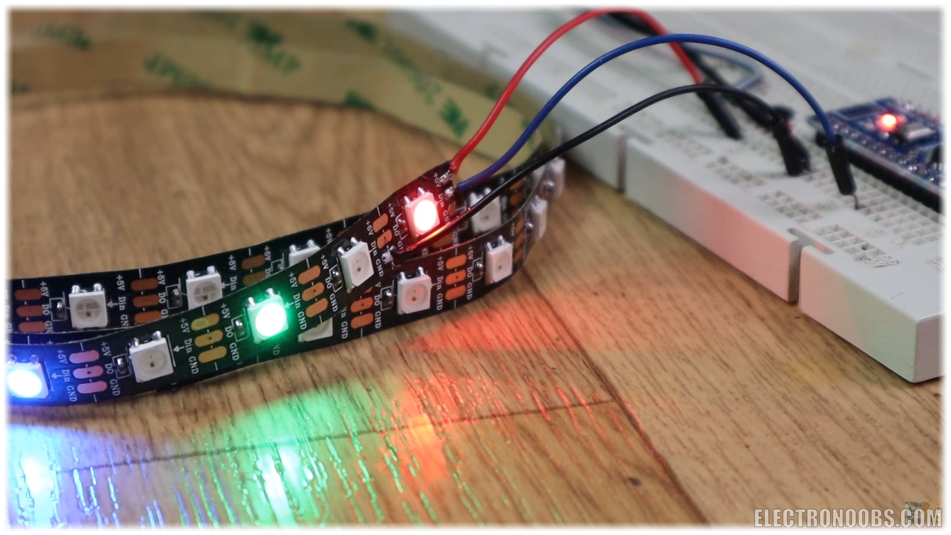
This below is the LED strip. It has RGB LEDs, where RGB stand for red, green and blue. By controlling the amount of each of these colors, we could obtain any color that we want. With a normal RGB strip, you should send a PWM signal to each LED and to each color of that LED in order to control brightness. But this LED strip (WS2812b) has an integrated chip for each diode.
As you can see below the basic one has 3 inputs for R, G and B. But the addressable one only a Din pin.
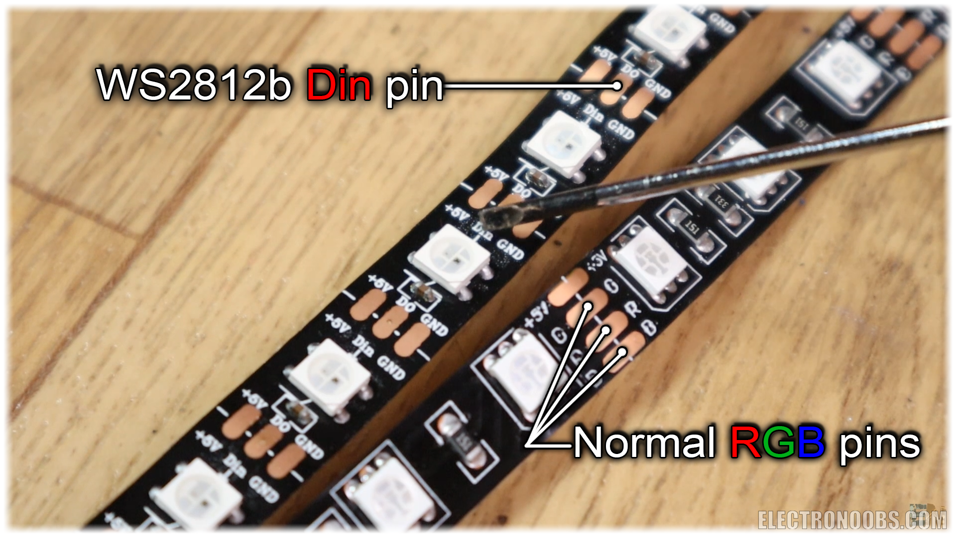
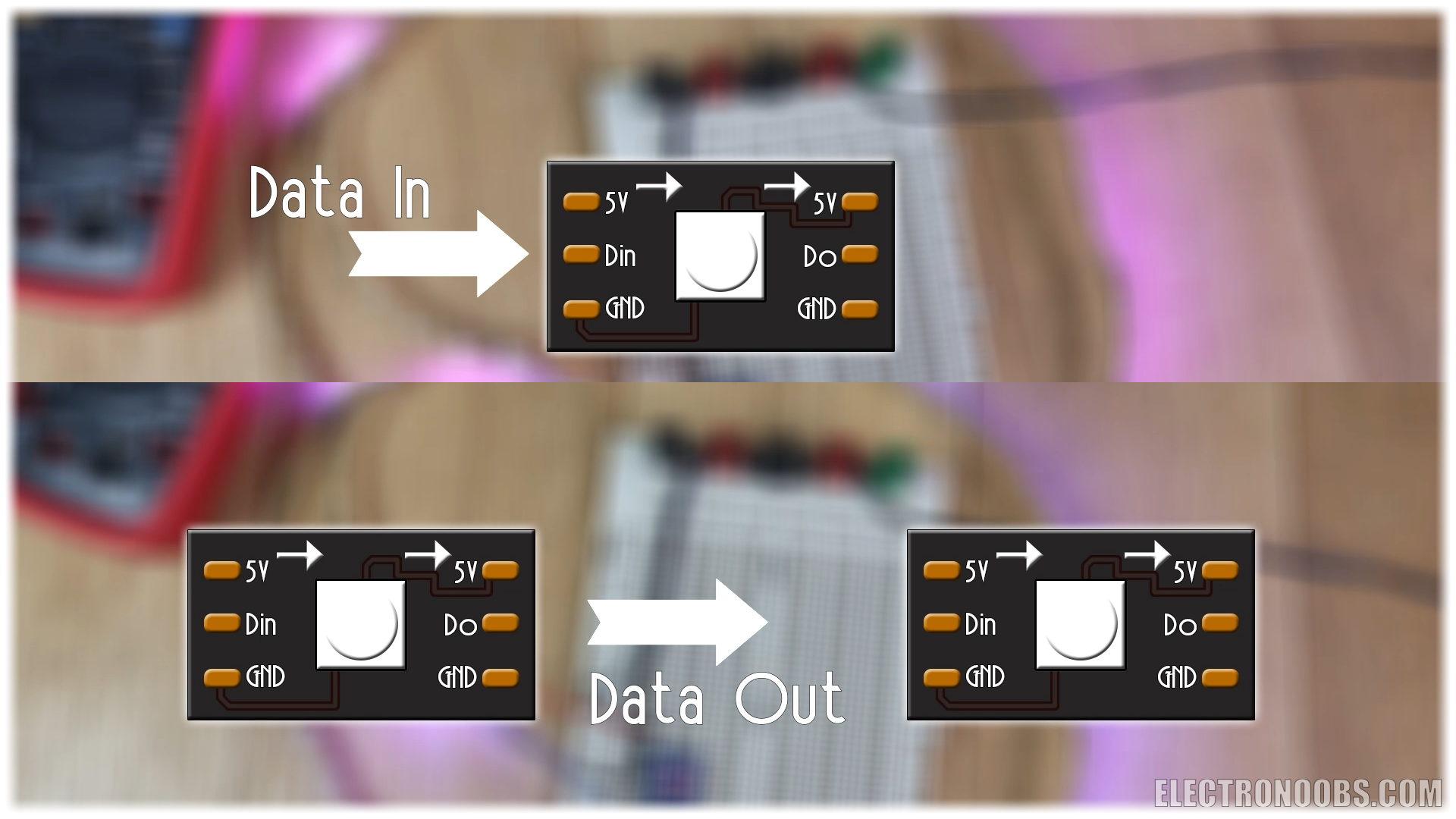
You should only send a digital signal to the data pin and the chip will do all the job according to the received data. The same data that enters the first chip on the D in pin, will exit on the D out pin and go to the next LED. So, with just one single pin from out microcontroller we can control each of the LEDs.
Only one thing. This resistance has to be very, very, low. Otherwise it would create a voltage droop big enough to affect the voltage on the load, and we don’t want that. For example, if you want to apply 5 volts to the load and there is a voltage drop of 2 volts on the resistor, you will only apply 3 volts to that load and you won’t want that. For that, I’ll use a 0.01 ohms resistor like this one below. Choose one that could withstand over 10W or 15W of power, so you could measure up to 1 amp at 12V.
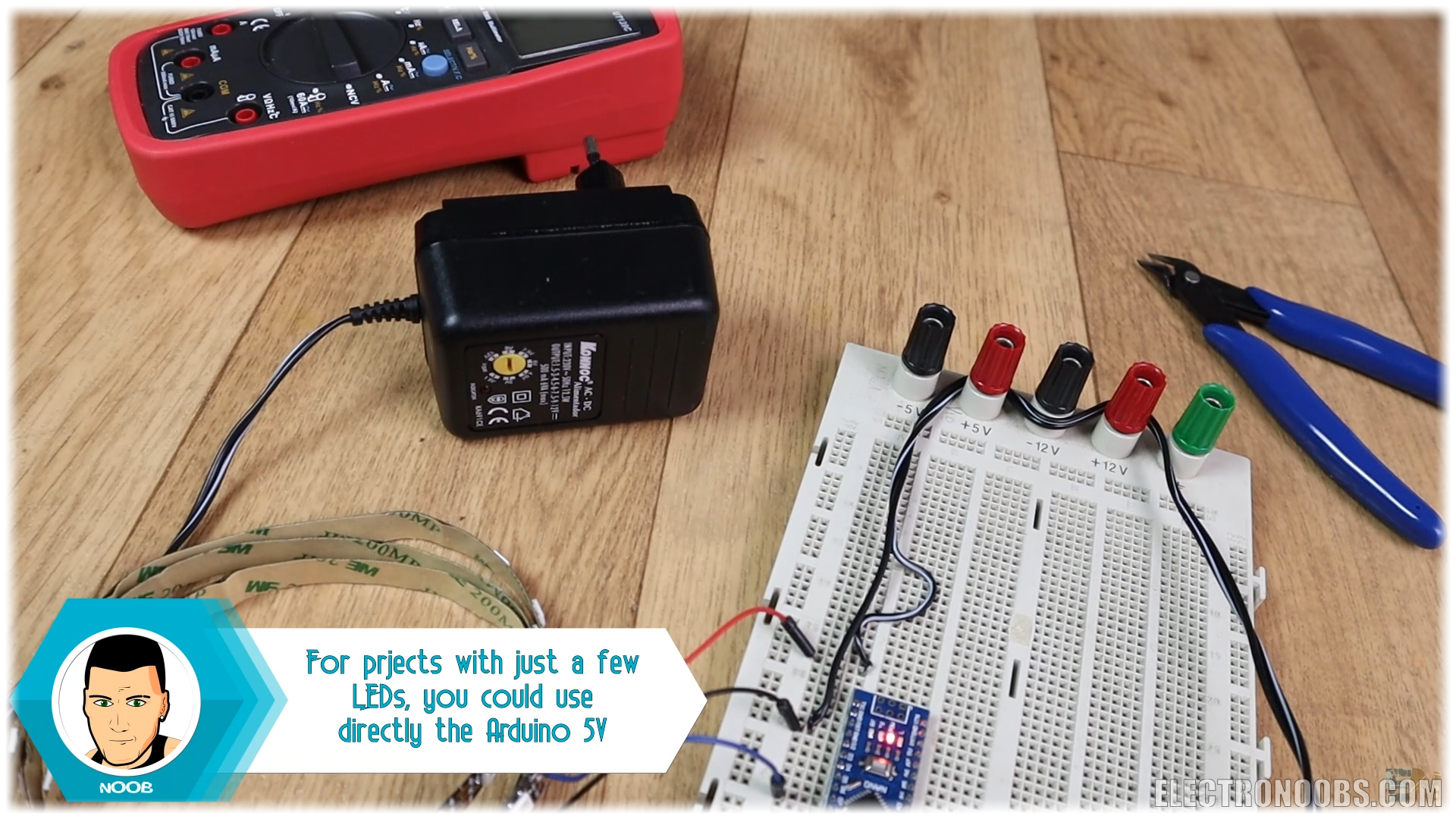
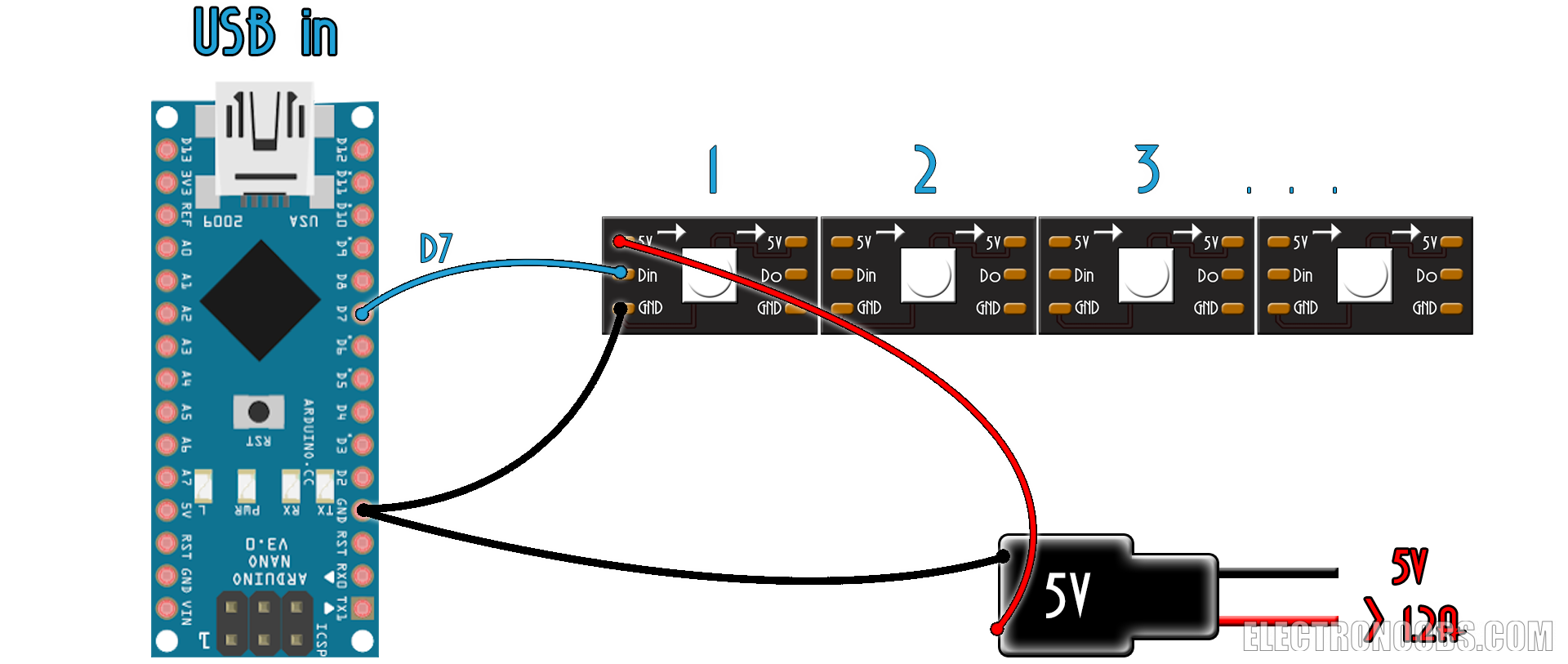
Connect the strip like this below. The data pin goes to any digital pin of the Arduino. In this case pin D7. Connect GND from the strip to the Arduino GND and the 5V pin to a 5V external power supply. Why we do this? Well each LED will draw around 20mA of current, and the Arduino 5V could only supply around 400mA. In my case, I have 60 LEDs, so it should draw up to 1.2 amps. For that we use an external supply of 5V. I’ve used the 5V dc transfoermer as in the part list. Also share ground between the transformer and the Arduino and we are good to go. If you put the ambilight to a desktop PC, you could get the 5V directly from any of the red wires of the power supply (Red=5V, Black=GND.
Now, open Arduino IDE. Go below and download the Fast Led library. You will download a zip file. Now go to sketch, include library, add .zip library and open the downloaded fast led file. Now the library is installed. Now download this test code from below as well.
#include <FastLED.h>
#define LED_PIN     7
#define NUM_LEDS    60
CRGB leds[NUM_LEDS];

void setup() {
  FastLED.addLeds<WS2812, LED_PIN, GRB>(leds, NUM_LEDS);

}
void loop() {

  leds[0] = CRGB(255, 0, 0);      //Red, green, blue
  FastLED.show();
  delay(1000);
  leds[2] = CRGB(0, 255, 0);
  FastLED.show();
  delay(1000);
  leds[4] = CRGB(0, 0, 255);
  delay(1000);
}As you can see this test example is easy. The library does everything for us. Define the pin used with the LED strip, in my case pin D7. Define the amount of LEDs that your strip has, in my case 60. Now all we have to do, is to select the led number with this vector and give the amount of color fore the reg, green and blue, where 0 is the LED turned off and 255 is maximum brightness of that color.
Good, I turn the red color of the first LED, the green of the second and blue of third, and then turn them off. Upload the code and let’s see the example. Easy right? With only one pin, we can control any amount of LEDs. Now let’s start with our project. I want to add the AMBILIGHT to my laptop. Since my work desktop screen already has an LED strip.
The first thing to do is to measure and divide the LED strip around the back of the screen. In my case I have a strip of 60 LEDs so I’ve placed 21 on the top side of the screen, and 14 on each side. Then I’ve placed 5 more LEDs on each bottom side like this. The strip already has glue on its back, so just peal that off and glue the LED’s on the back of your screen. Make sure you follow the arrows on the LED stip and not put is backwards.
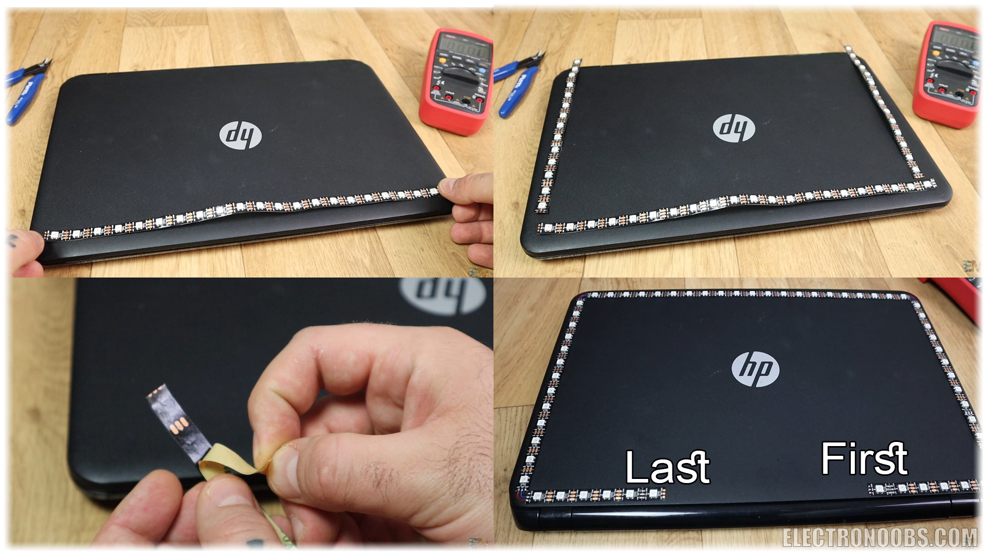
Now, I solder connections on the corners between each line of LED knowing the first and last LEDs and following the arrows on the LED strip. When all the sides are connected, I solder the first data pin from the LED strip to Digital pin D7 of an Arduino NANO, and ground to ground.
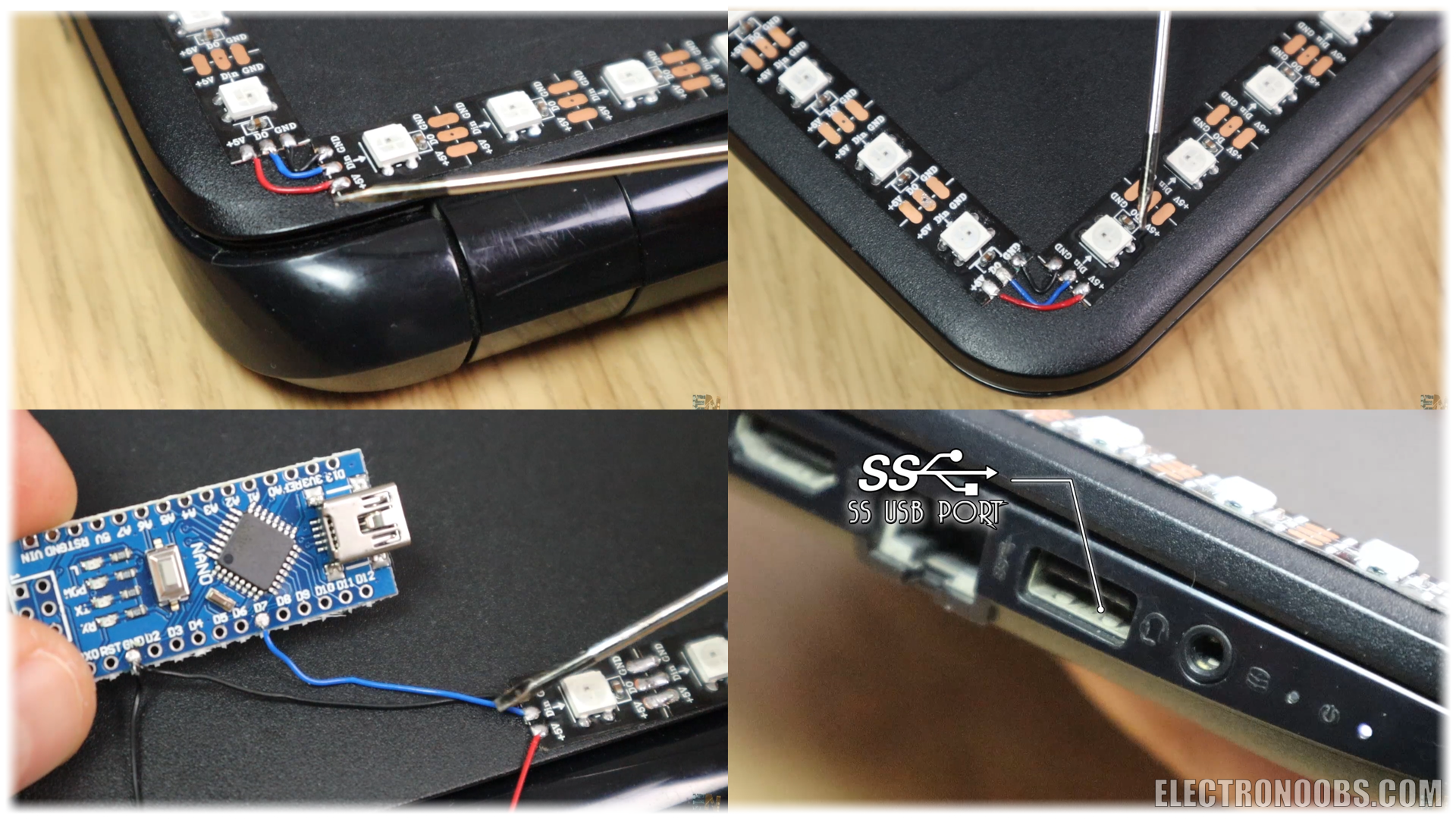
Now, my laptop has an SS USB output with up to 1.5 amps, so since the USB is directly connected to the 5V pin and not passing through any regulator, I won’t use the external power supply for now. I solder the 5V wire directly to the Arduino 5V. If you make the same setup for a bigger screen and more LEDs, or not having an SS USB port, make sure to connect the 5V and GND to and external supply to a 5V transformer. I connect the USB to the Arduino and then power it to the USB port.
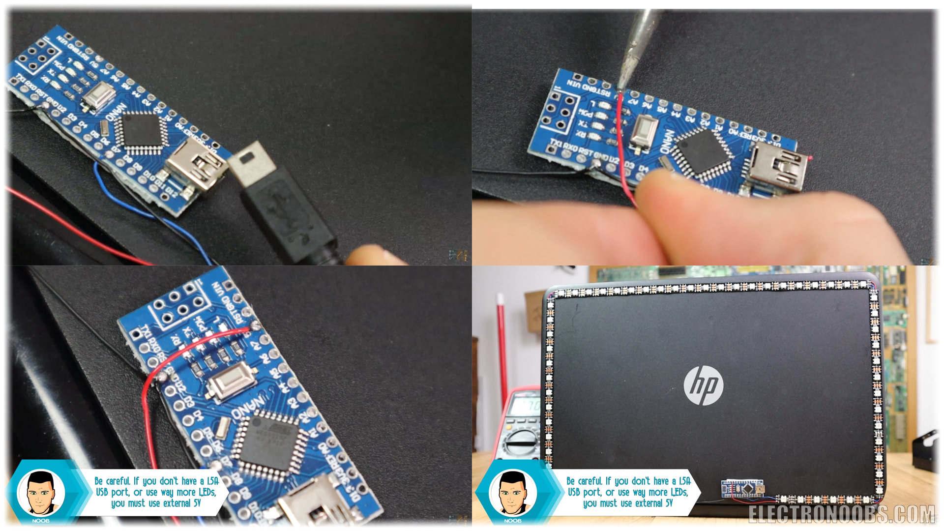
Go below and download the Adalight code for the Arduino. Open it in the Arduino IDE and make sure you have already installed the FastLED library before. There in the code, all we have to do is to define the pin, in my case digital pin 7, and amount of LEDs, in my case 59. Compile, select the COM port and upload the code to the Arduino.
/*
 * Arduino interface for the use of WS2812 strip LEDs
 * Uses Adalight protocol and is compatible with Boblight, Prismatik etc...
 * "Magic Word" for synchronisation is 'Ada' followed by LED High, Low and Checksum
 * @author: Wifsimster <wifsimster@gmail.com>
 * @library: FastLED v3.001
 * @date: 11/22/2015
 */
#include "FastLED.h"
#define NUM_LEDS 240
#define DATA_PIN 7

// Baudrate, higher rate allows faster refresh rate and more LEDs (defined in /etc/boblight.conf)
#define serialRate 115200

// Adalight sends a "Magic Word" (defined in /etc/boblight.conf) before sending the pixel data
uint8_t prefix[] = {'A', 'd', 'a'}, hi, lo, chk, i;

// Initialise LED-array
CRGB leds[NUM_LEDS];

void setup() {
  // Use NEOPIXEL to keep true colors
  FastLED.addLeds<NEOPIXEL, DATA_PIN>(leds, NUM_LEDS);

  // Initial RGB flash
  LEDS.showColor(CRGB(255, 0, 0));
  delay(500);
  LEDS.showColor(CRGB(0, 255, 0));
  delay(500);
  LEDS.showColor(CRGB(0, 0, 255));
  delay(500);
  LEDS.showColor(CRGB(0, 0, 0));

  Serial.begin(serialRate);
  // Send "Magic Word" string to host
  Serial.print("Ada\n");
}

void loop() {
  // Wait for first byte of Magic Word
  for(i = 0; i < sizeof prefix; ++i) {
    waitLoop: while (!Serial.available()) ;;
    // Check next byte in Magic Word
    if(prefix[i] == Serial.read()) continue;
    // otherwise, start over
    i = 0;
    goto waitLoop;
  }

  // Hi, Lo, Checksum
  while (!Serial.available()) ;;
  hi=Serial.read();
  while (!Serial.available()) ;;
  lo=Serial.read();
  while (!Serial.available()) ;;
  chk=Serial.read();

  // If checksum does not match go back to wait
  if (chk != (hi ^ lo ^ 0x55)) {
    i=0;
    goto waitLoop;
  }

  memset(leds, 0, NUM_LEDS * sizeof(struct CRGB));
  // Read the transmission data and set LED values
  for (uint8_t i = 0; i < NUM_LEDS; i++) {
    byte r, g, b;
    while(!Serial.available());
    r = Serial.read();
    while(!Serial.available());
    g = Serial.read();
    while(!Serial.available());
    b = Serial.read();
    leds[i].r = r;
    leds[i].g = g;
    leds[i].b = b;
  }

  // Shows new values
  FastLED.show();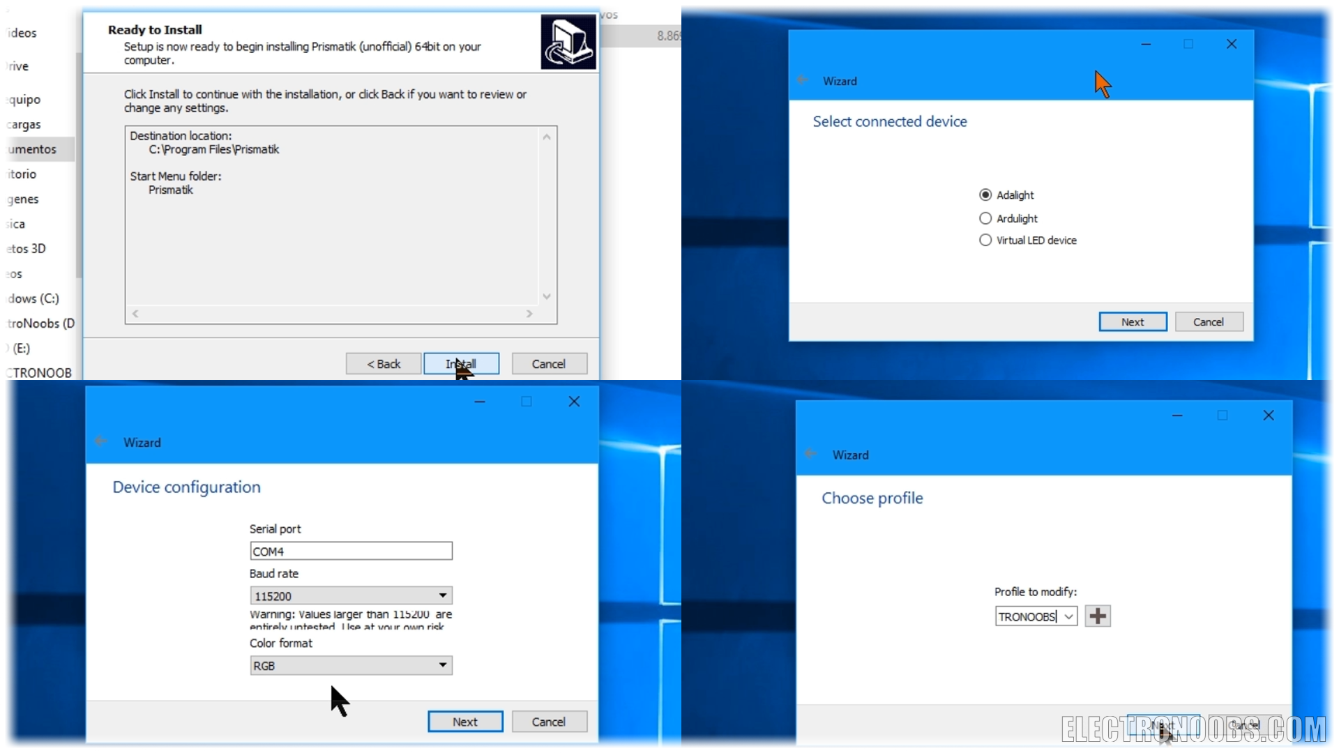
}Now download from below the Prismatic software. This will generate the data for the perimeter colors of our screen. Install it following the default settings. You may want to start the installation as an admin, otherwise your windows might not let you install it.
Now run the application. The first time you run it, you will get the configuration wizard. Select Adalight and click next. There, select the USB com that you are using for the Arduino board (COM4 in my case). The baud rate has to be the same as here in the code that we have uploaded before, in this case 115200. Select RGB color format and click next. Give a name to your setup, I’ll name it ELECTRONOOBS.
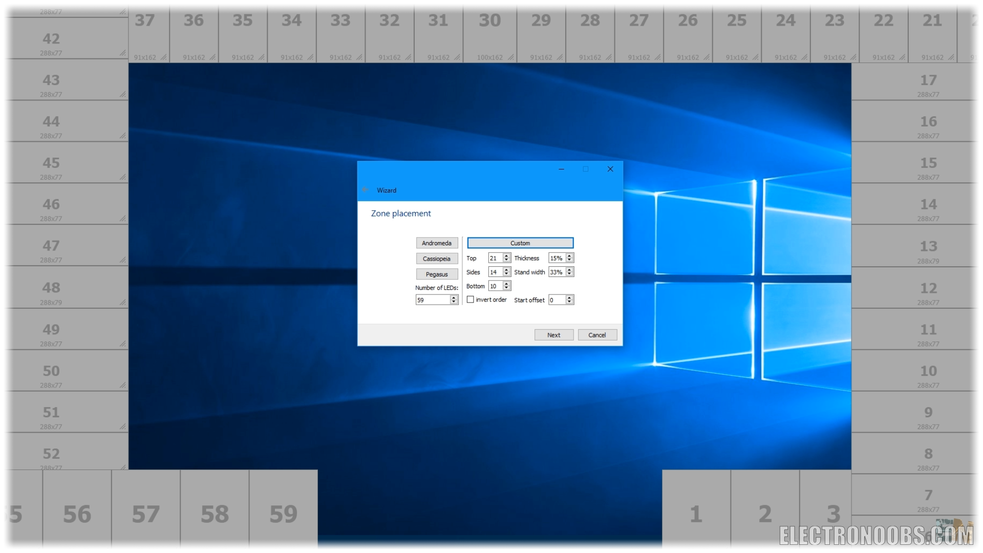
Now, here is the interesting part. Define the amount of LEDs you have on the top part. In my case, I’ve placed 21 on the top part of the screen. 14 on the sides and 10 on the bottom. Click custom and see how this will look like. The stand offset will give you the space between this bottom LEDs. If you have a full perimeter, live this to 0 percent. You could customize this as you please manually. I live it like this for now.
Press next and here adjust each color till you match the color of your background wall, in my case white. Click next and we are done. Now play any RGB test video that you’ll fint in the description and there you go. You can now watch movies with AMBILIGHT effects and that is awesome. The application also has sound effect where the LEDs will blink according to the music you play.
Well guys, there you have it. I hope that you’ve enjoyed this tutorial and learn something new about addressable LEDs control. The tutorial is very easy and the schematic is just a few connections, but this project looks so cool. If you would like to support my projects, check my PATREON page link, I would really appreciate that guys, Thanks to you all.
Comments


Leave a comment
Please login in order to comment.