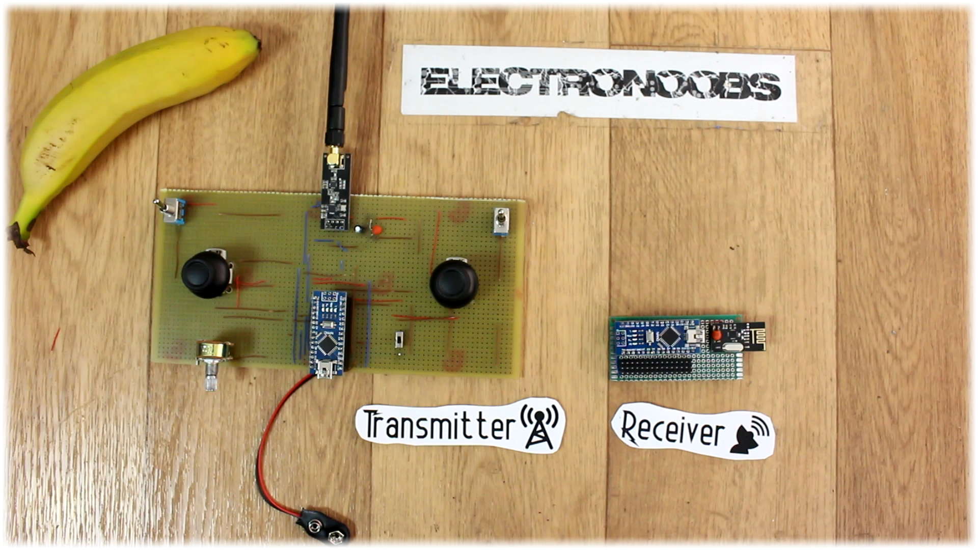
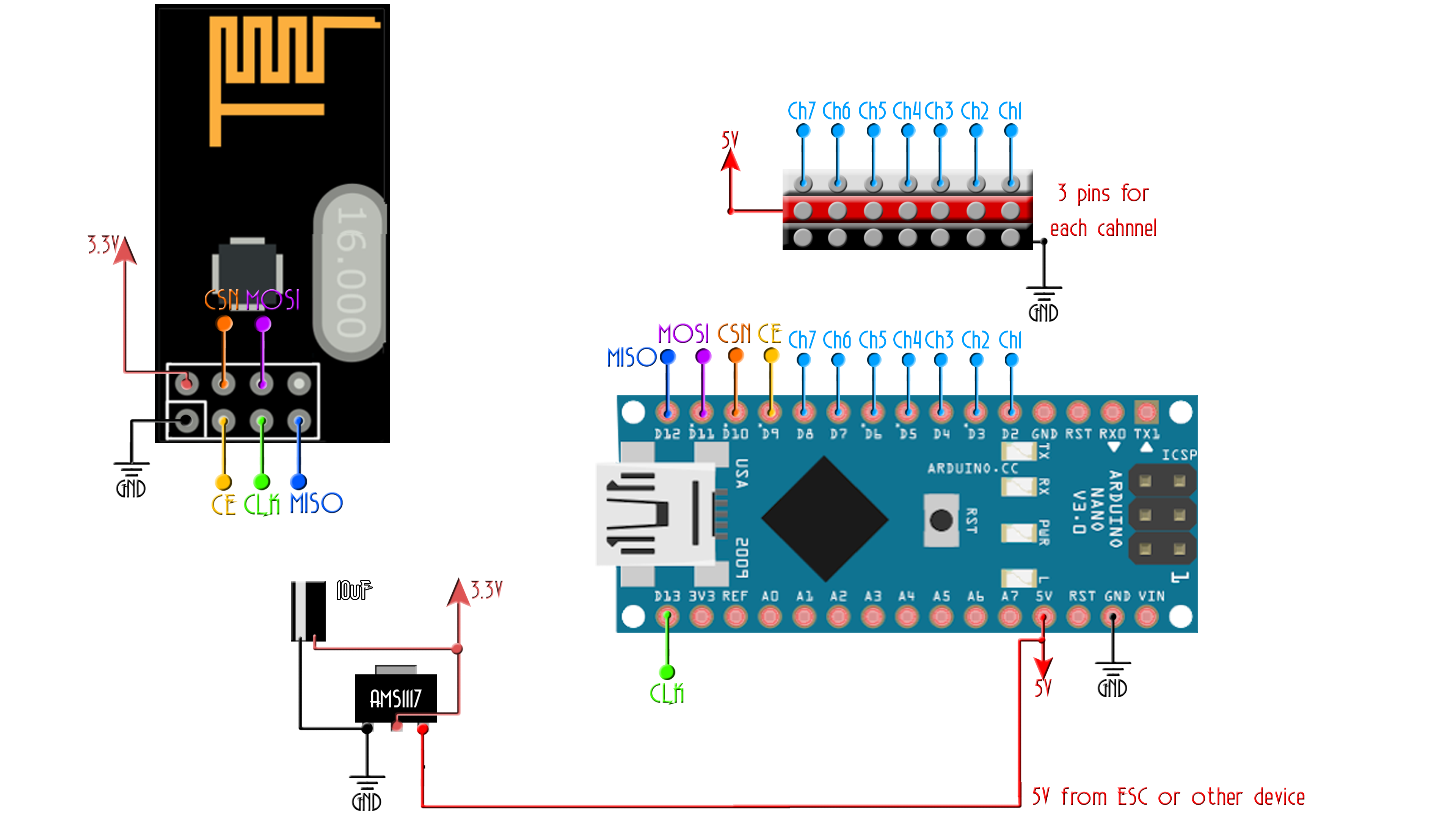
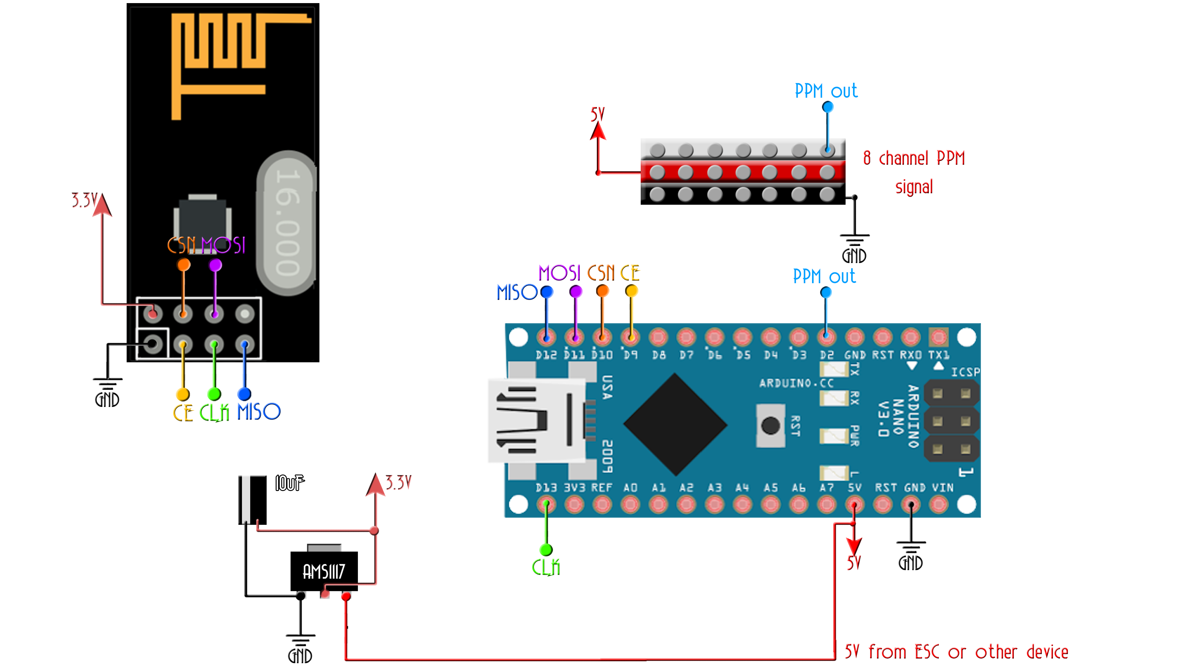
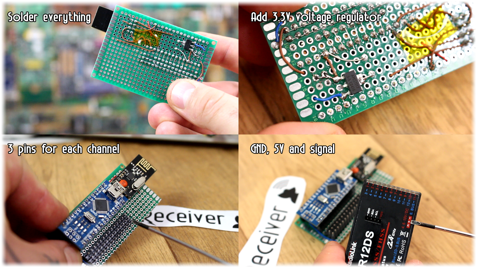
Well, we have the transmitter. Now let’s build the receiver. That should be quite easy. All we need is the Arduino NANO, a NRF24 receiver like this one, another 3.3 voltage regulator and a small PCB. We will use the schematic below. You will see two schematics. They are more than the same but one has 7 PWM outputs and the other only one PPM output. Depending on the project that you want use one or the other.
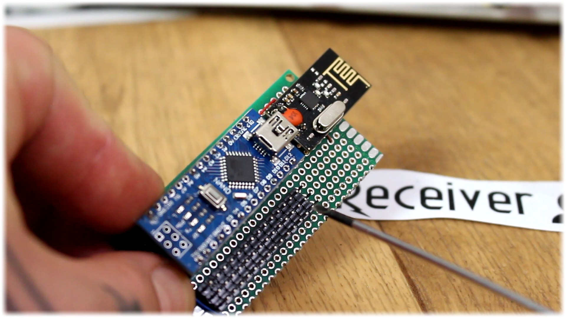
Ok so I’ve soldered everything in place. The Arduino and the voltage regulator and made connections to the radio module. The receiver won’t need a battery supply, since just as any other commercial receiver, it will be supplied with directly 5V as you can see below on the commercial receiver that has ground, 5V and signal. Now, you see, the commercial receiver has 90 degrees pins for each channel. I don’t have that now so I’ve used normal straight pcb pins. Place 3 pins for each channel. Ground, 5V and signal. This kind of connection could have up to 32 channels, which is the maximum supported by the NRF24 modules, but the Arduino doesn’t have that much digital pins. Now we are ready to program both the transmitter and receiver.
Now, download the transmitter and receiver codes. Be careful, there are two receiver codes, one for PWM and the other for PPM. I’ll use PWM for now. First let's talk a bit about the transmitter code. It will send 7 channels. We read the analog and digital values from the radio controller, create 7 bytes and sent that data.
Ok, let's talk about the transmitter code. Let me explain it to you step by step. First, we import the library that we need.
Next, we define the radio pipe. This code should be the same in the transmitter and receiver since it is a unique code for the radio connections. Having multiple receivers with this same pipe code, they will all receive the same data from the transmitter.
Next, we define the chip select and chip enable pins for the SPI communication. This two could be any digital pin of the Arduino. In this case are pins 9 and 10. The other SPI pins must be digital 11, 12 and 13 since those are the clock, MOSI and MISO ports of the Arduino and they can’t be other pins.
//Import libraries
#include <SPI.h>
#include <nRF24L01.h>
#include <RF24.h>

const uint64_t my_radio_pipe = 0xE8E8F0F0E1LL; //Remember that this code should be the same for the receiver
//Define CE and CSN pins. CLK, MOSI, MISO must be D13, B11 and D12
RF24 radio(9, 10);	//These pins could be any digital pin of the Arduino

// The sizeof this struct should not exceed 32 bytes
struct Data_to_be_sent {
  byte ch1;
  byte ch2;
  byte ch3;
  byte ch4;
  byte ch5;
  byte ch6;
  byte ch7;
};

//Create a variable with the structure above and name it sent_data
Data_to_be_sent sent_data;
Now, we create a structure type variable and store each channel value in this structure. This could have up to 32 channels, each of 8 bits or better said one byte. I name each channel, from channel 1 to 7.
Now we create a variable with that structure and name it sent data and this will be the package that we will send.
Ok, in the setup void we begin the radio communication using the begin function that the NRF24 library already has. We set the radio communication configuration and open the radio pipe, with the variable: my radio pipe defined before. The next lines will reset the channel values.
void setup()
{
  radio.begin();
  radio.setAutoAck(false);
  radio.setDataRate(RF24_250KBPS);
  radio.openWritingPipe(my_radio_pipe);

  //Reset each channel value
  sent_data.ch1 = 127;
  sent_data.ch2 = 127;
  sent_data.ch3 = 127;
  sent_data.ch4 = 127;
  sent_data.ch5 = 0;
  sent_data.ch6 = 0;
  sent_data.ch7 = 0;
}
In this case, all 4 potentiometers of the joysticks will be in the middle position. Since we can only send 8 bites per channel, which in decimal is 255, well the middle of 255 will be 127, that’s why I reset channel 1 to 4 with these values. Next, we have two digital channels, channel 5 and 6 with values of 0 or 1. And finally another analog channel but with value 0 since it will be connected to a potentiometer that will have its initial position to 0.
void loop()
{
  /*If your channel is reversed, just swap 0 to 255 by 255 to 0 below
  EXAMPLE:
  Normal:    data.ch1 = map( analogRead(A0), 0, 1024, 0, 255);
  Reversed:  data.ch1 = map( analogRead(A0), 0, 1024, 255, 0);  */

  sent_data.ch1 = map( analogRead(A0), 0, 1024, 0, 255);
  sent_data.ch1 = map( analogRead(A1), 0, 1024, 0, 255);
  sent_data.ch1 = map( analogRead(A2), 0, 1024, 0, 255);
  sent_data.ch1 = map( analogRead(A3), 0, 1024, 0, 255);
  sent_data.ch1 = digitalRead(2);
  sent_data.ch1 = digitalRead(3);
  sent_data.ch1 = map( analogRead(A4), 0, 1024, 0, 255);

  radio.write(&sent_data, sizeof(Data_to_be_sent));
}
Finally, in the void loop, we read each analog and digital inputs, which in this case are Analog pins A0 to A4 and digital pins D2 and D3. We map the values to a range between 0 and 255 since we can only send 8 bits and store the value in our sent_data variable and we send the entire structure using the radio.write function.
Ok, so the code was very simple. Now let’s take a look on to the receiver side. It is a bit longer but that is because each line is repeating for each channel.
Once again import the needed libraries, in this case the servo library as well for the PWM signals. Define the pipe as in the transmitter code and the chip select and enable pins.
Again, we create the 7 bytes structure for the received values. Now, we create 7 servo types and define the PWM initial value for each channel. In the setup loop we attach the PWM signal to pins from digital D2 to D8. Finally, we configure the radio connection and start listening.
void setup()
{
  //Attach the servo signal on pins from D2 to D8
  channel_1.attach(2);
  channel_2.attach(3);
  channel_3.attach(4);
  channel_4.attach(5);
  channel_5.attach(6);
  channel_6.attach(7);
  channel_7.attach(8);

  //We reset the received values
  received_data.ch1 = 127;
  received_data.ch2 = 127;
  received_data.ch3 = 127;
  received_data.ch4 = 127;
  received_data.ch5 = 0;
  received_data.ch6 = 0;
  received_data.ch7 = 0;

  //Once again, begin and radio configuration
  radio.begin();
  radio.setAutoAck(false);
  radio.setDataRate(RF24_250KBPS);
  radio.openReadingPipe(1,pipeIn);

  //We start the radio comunication
  radio.startListening();

}
Next, we have this function called receive_the_data. This function will receive the data and store it in our structure created before. In the void loop we use the receive data to get the values. Then we will map the received values from 8 bits to values from 1000 to 2000us since those are usually the values that any commercial radio receivers use for the PWM signal.
//We create the function that will read the data each certain time
void receive_the_data()
{
  while ( radio.available() ) {
  radio.read(&received_data, sizeof(Received_data));
  last_Time = millis(); //Here we receive the data
}
}
We read the received data, map the values to a range of 1000-2000us and then using the writeMicroseconds function, we create each of the 7 PWM signals as you can see below and we are done. Now we can upload the codes to the receiver and transmitter and test the connection.
  ch5_value = map(received_data.ch5,0,1,1000,2000);
  ch6_value = map(received_data.ch6,0,1,1000,2000);
  ch7_value = map(received_data.ch7,0,255,1000,2000);

  //Creathe the PWM signals
  channel_1.writeMicroseconds(ch1_value);
  channel_2.writeMicroseconds(ch2_value);
  channel_3.writeMicroseconds(ch3_value);
  channel_4.writeMicroseconds(ch4_value);
  channel_5.writeMicroseconds(ch5_value);
  channel_6.writeMicroseconds(ch6_value);
  channel_7.writeMicroseconds(ch7_value);


}//Loop end