So now that we know how to read the real temperature, let’s mount this next schematic and control the power applied to the heating element with a MOSFET. I mount the circuit on a breadboard once again and upload the next code. This second code has the PID algorithm already created. We read the temperature, calculate the error, sum the PID values and create a PWM signal on digital pin D3 that will be applied to the MOSFET. I set the desired temperature at 100 degrees and use the LCD to print the set value and the real temperture.
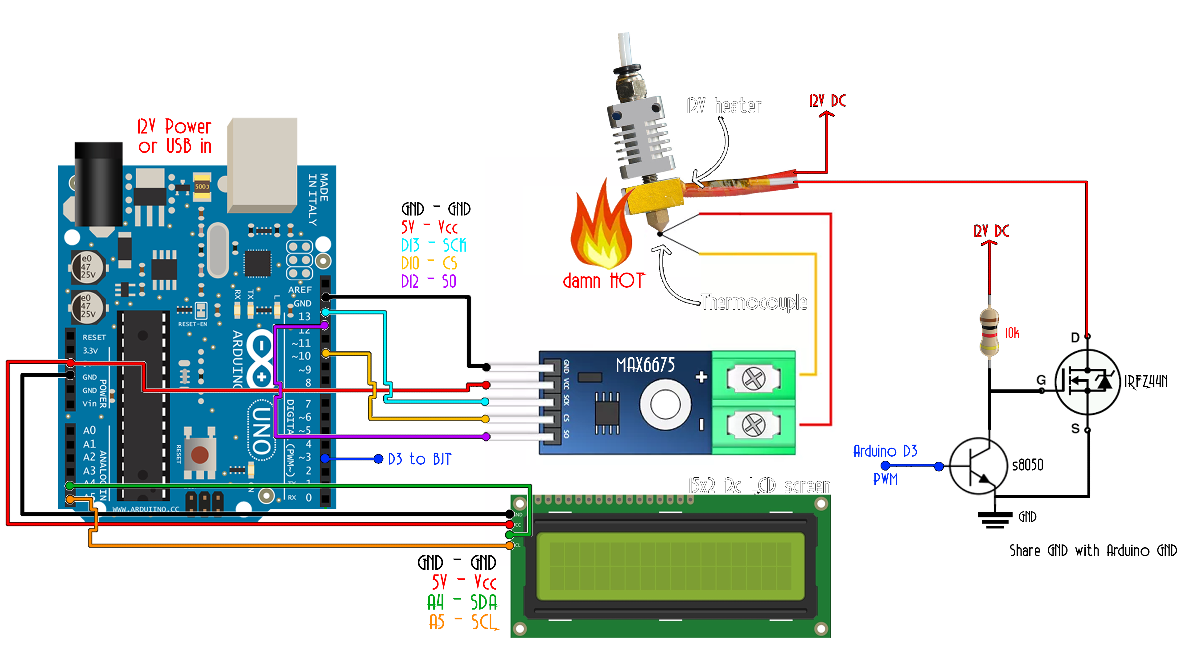
Ok so the code below is a bit large. But don't worry. It is very easy. We set a variable setpoint at 100 degrees for this example. Then we read the thermocouple real temperature value as in the past example. Then we use 3 constants and calculate the PID sum. Depending on that value we create a PWM signal on pin D3 and apply it to the MOSFET gate using a BJT driver.
/*    Max6675 Module  ==>   Arduino
 *    CS              ==>     D10
 *    SO              ==>     D12
 *    SCK             ==>     D13
 *    Vcc             ==>     Vcc (5v)
 *    Gnd             ==>     Gnd      */

//LCD config (i2c LCD screen, you need to install the LiquidCrystal_I2C if you don't have it )
#include <Wire.h>
#include <LiquidCrystal_I2C.h>
LiquidCrystal_I2C lcd(0x3f,20,4);  //sometimes the adress is not 0x3f. Change to 0x27 if it dosn't work.

/*    i2c LCD Module  ==>   Arduino
 *    SCL             ==>     A5
 *    SDA             ==>     A4
 *    Vcc             ==>     Vcc (5v)
 *    Gnd             ==>     Gnd      */

#include <SPI.h>
//We define the SPI pìns
#define MAX6675_CS   10
#define MAX6675_SO   12
#define MAX6675_SCK  13

//Pins
int PWM_pin = 3;


//Variables
float temperature_read = 0.0;
float set_temperature = 100;
float PID_error = 0;
float previous_error = 0;
float elapsedTime, Time, timePrev;
int PID_value = 0;


//PID constants
int kp = 9.1;   int ki = 0.3;   int kd = 1.8;
int PID_p = 0;    int PID_i = 0;    int PID_d = 0;


void setup() {
  pinMode(PWM_pin,OUTPUT);
  TCCR2B = TCCR2B & B11111000 | 0x03;    // pin 3 and 11 PWM frequency of 980.39 Hz
  Time = millis();
  lcd.init();
  lcd.backlight();
}


void loop() {
 // First we read the real value of temperature
  temperature_read = readThermocouple();
  //Next we calculate the error between the setpoint and the real value
  PID_error = set_temperature - temperature_read;
  //Calculate the P value
  PID_p = kp * PID_error;
  //Calculate the I value in a range on +-3
  if(-3 < PID_error <3)
  {
    PID_i = PID_i + (ki * PID_error);
  }

  //For derivative we need real time to calculate speed change rate
  timePrev = Time;                            // the previous time is stored before the actual time read
  Time = millis();                            // actual time read
  elapsedTime = (Time - timePrev) / 1000;
  //Now we can calculate the D calue
  PID_d = kd*((PID_error - previous_error)/elapsedTime);
  //Final total PID value is the sum of P + I + D
  PID_value = PID_p + PID_i + PID_d;

  //We define PWM range between 0 and 255
  if(PID_value < 0)
  {    PID_value = 0;    }
  if(PID_value > 255)
  {    PID_value = 255;  }
  //Now we can write the PWM signal to the mosfet on digital pin D3
  analogWrite(PWM_pin,255-PID_value);
  previous_error = PID_error;     //Remember to store the previous error for next loop.

  delay(300);
  //lcd.clear();

  lcd.setCursor(0,0);
  lcd.print("PID TEMP control");
  lcd.setCursor(0,1);
  lcd.print("S:");
  lcd.setCursor(2,1);
  lcd.print(set_temperature,1);
  lcd.setCursor(9,1);
  lcd.print("R:");
  lcd.setCursor(11,1);
  lcd.print(temperature_read,1);
}


double readThermocouple() {

  uint16_t v;
  pinMode(MAX6675_CS, OUTPUT);
  pinMode(MAX6675_SO, INPUT);
  pinMode(MAX6675_SCK, OUTPUT);

  digitalWrite(MAX6675_CS, LOW);
  delay(1);

  // Read in 16 bits,
  //  15    = 0 always
  //  14..2 = 0.25 degree counts MSB First
  //  2     = 1 if thermocouple is open circuit
  //  1..0  = uninteresting status

  v = shiftIn(MAX6675_SO, MAX6675_SCK, MSBFIRST);
  v <<= 8;
  v |= shiftIn(MAX6675_SO, MAX6675_SCK, MSBFIRST);

  digitalWrite(MAX6675_CS, HIGH);
  if (v & 0x4)
  {
    // Bit 2 indicates if the thermocouple is disconnected
    return NAN;
  }

  // The lower three bits (0,1,2) are discarded status bits
  v >>= 3;

  // The remaining bits are the number of 0.25 degree (C) counts
  return v*0.25;
}
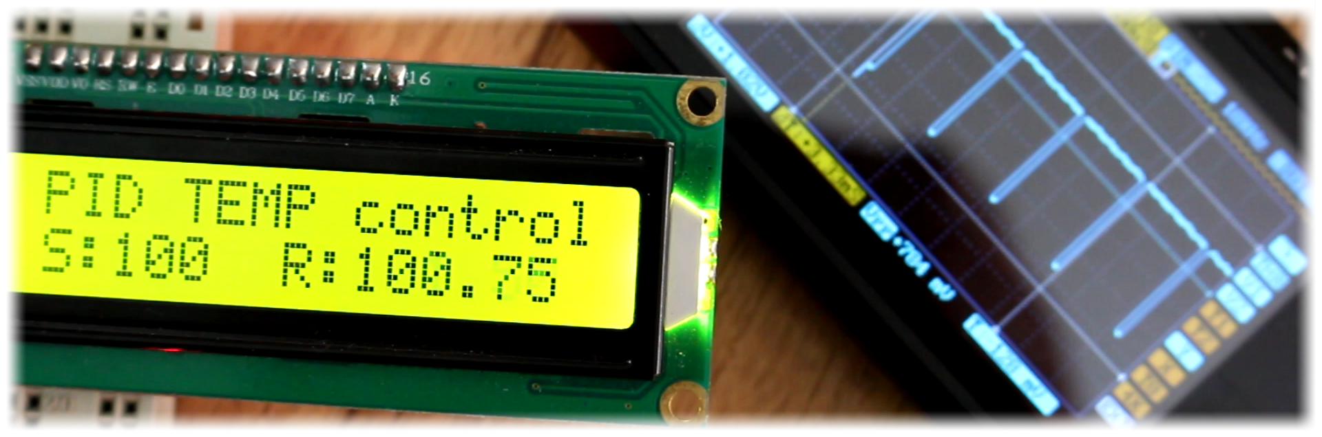
As you can see the temperature stays at that value. But that is after trying a lot of PID constants and that is the tricky part of this project. So, what you will have to do is try your own values till you get the correct ones. I advise you to start with the I and D values equal 0 and then increase those values slowly till you get good results.
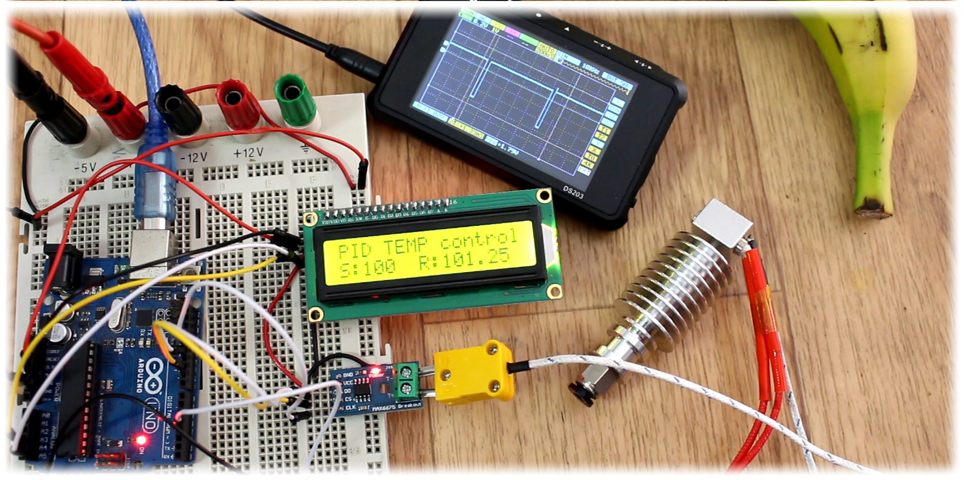
Here on my oscilloscope I have the PWM signal of the MOSFET connected.
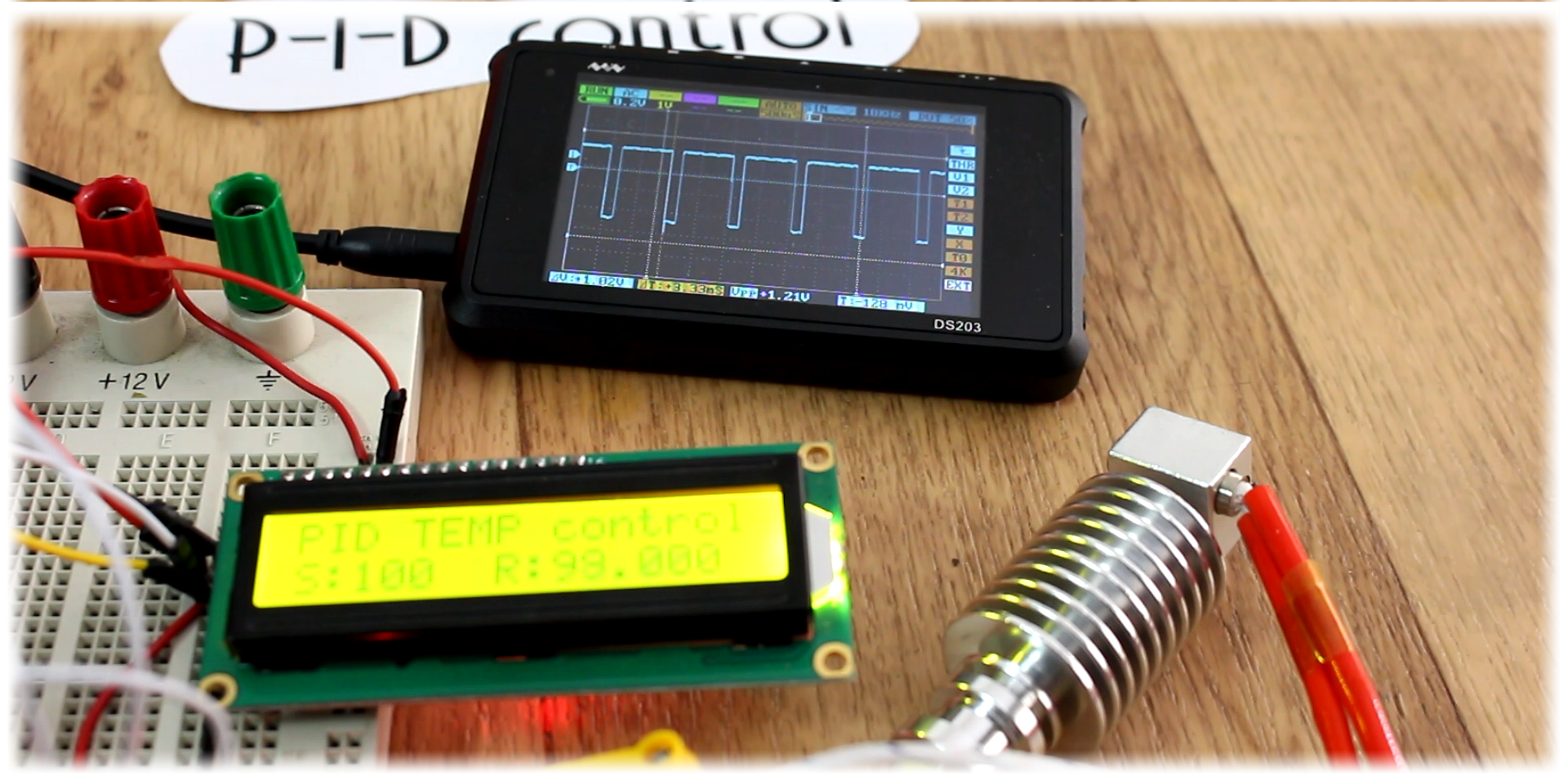
At the beginning, till the system reaches the desired value the pulse has a small width since I use a BJT to activathe the N channel gate, so the mosfet is activated with a LOW value in this case. Once the set value is reached it starts to wambble around and by that maintaining the temperature. As you can see, if I try to cool down the heating element by blowing air with this tube, the PWM signal width get’s lower in order to keep the same value. So, the control works.
Now, all this system needs is some sort of control togheter with the LCD screen in order to view and also be able to set the desired temperature value as this commercial PID controller has the set and up and down buttons. For that I'll use the rotary encoder. It has a push button integrated so I can use it to enter the setpoint menu and increase or decrease the value.
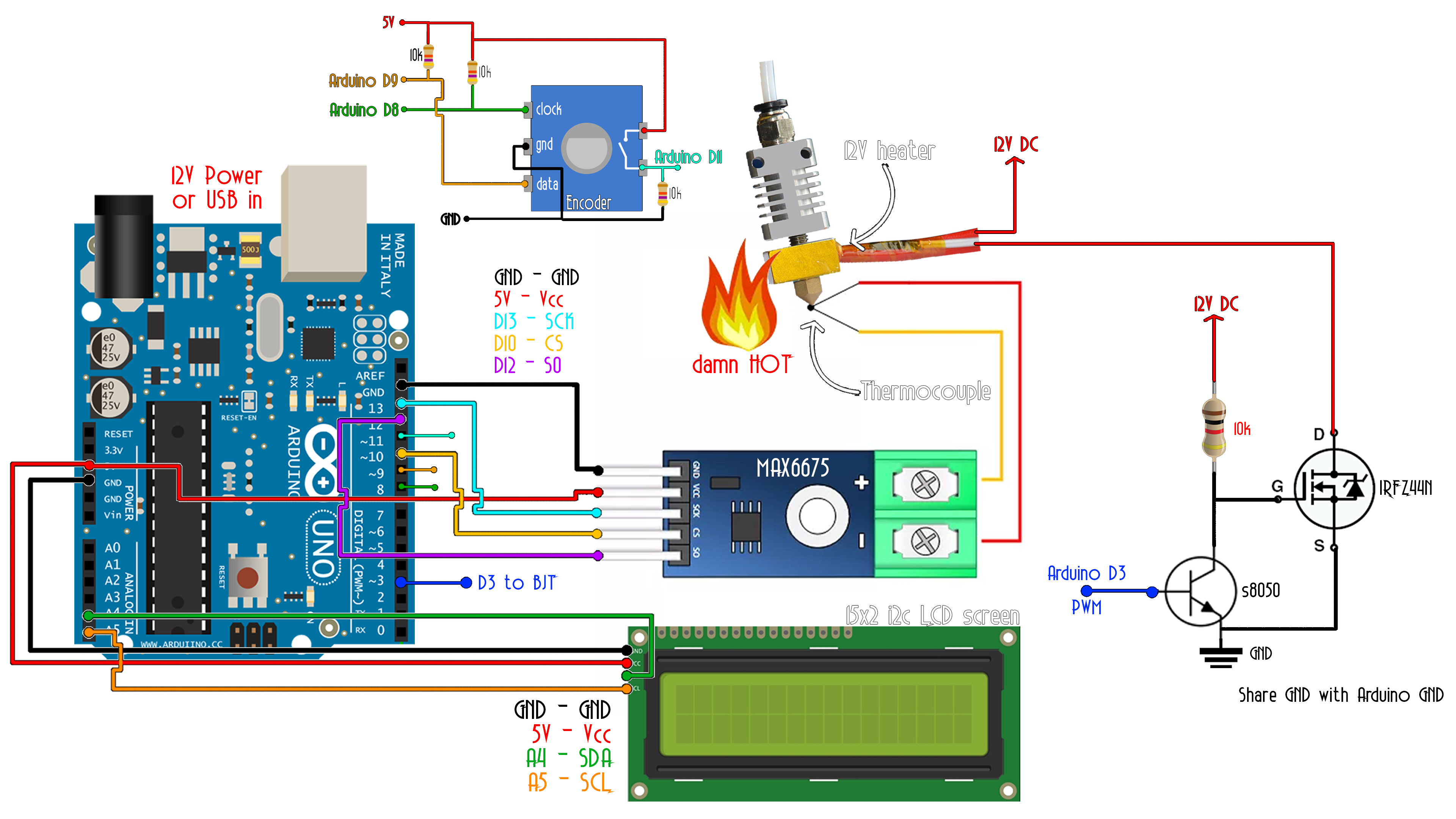
This above is the final schematic of this project. We have an LCD screen to print the values, the rotary encoder with push button insede for control, the thermocouple with the MAX 66 75 module, the MOSFET and the BJT as a driver circuit that will control the power and the heating element. Make sure that the thermocouple is touching the heating element in order to know the real value. I mount everything on the breadboard and now let’s test the new code, which by the way, you can also download from a below.
The default value is now 0 degrees. Press the set button of the rotary encoderRotate it to the left in order to increase or decrease the temperature value. Press the set button once again and now you can set the P constant for the PID control. Press once again and select the I value. Finally, press the button again and select the D value. Now press the button and exit the menu and the new settings are stored. I set it to 100 degrees and now the real read starts increasing till it reaches the desired value and it stays there. When we reach the desired value you can see the PWM wombelling in order to maintain that value.
There you go our PID of temperature works. I could 3D print a case for this project just as the commercial one has, but, since I’ll use this project for my soldering station in a future tutorial, I won’t do that now. In a future project, I’ll use this 12V soldering iron with a thermocouple inside and make my own soldering station so stay tuned for that guys.
Have in mind that today’s project is for only DC power control, so only DC heating elements will work. I’ll also make a tutorial on a temperature PID control, but for AC 220V voltage using a TRIAC control as in the past TRIAC tutorial.
If my videos/tutorials help you and you would like to help my projects, I have a Patreon campaign. I would really appreciate that guys and it will help my workshop for other new projects and keep this channel/webpage going. BTW, thanks to all my Patreons.
I hope that you’ve enjoyed this small tutorial on PID control. If you have any question about this video or any other, just leave it in the comment section below or on my Q&A page. Also, don’t forget to subscribe and watch all of my other great tutorials. Remember, if you consider helping my projects check my Patreon page as well.