What’s up my friends, welcome back. This project requires 2 PCBs, one for the light switch and another PCB that will receive the radio command and turn on and off a relay (SSR in this case). The transmitter PCB has a 433MHZ crystal and a simple circuit to send data. The data is created by an ATTiny85. The receiver uses a radio module and depending on the received data, it will turn on and off a relay for 220V AC.
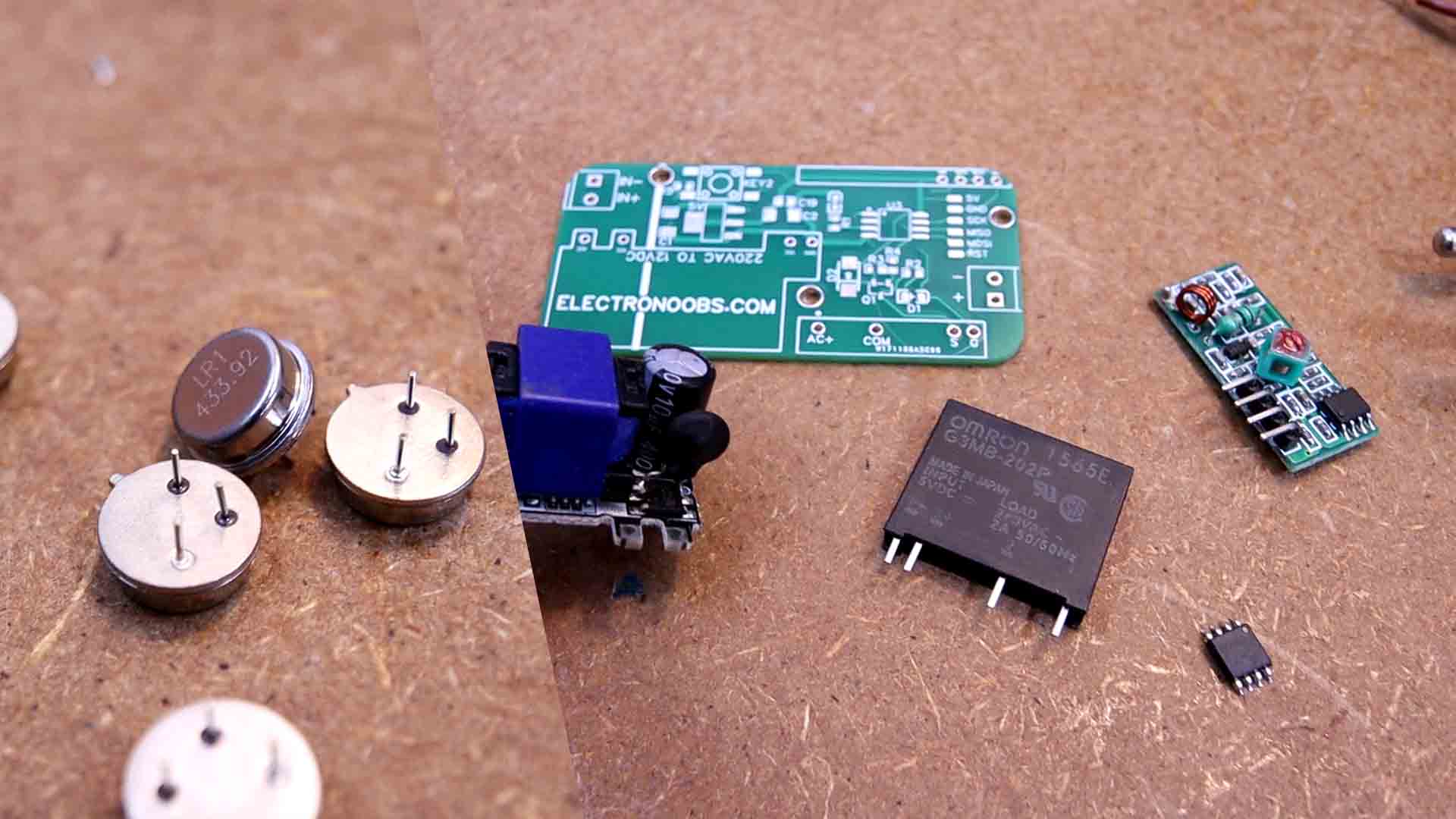
Obviouslly, you could make a prototype on a homemade PCB if you want. But is better to use my PCB. So get the GERBER files and order the PCBs at PCBWAY.com. for example. Once you have the PCBs, check the part list below. We need two ATTiny in an SMD format, some resistors and capacitors, coils, crystal resonators, buttons, the relay and a 220V to 12V converter. A few other components and a small 12V battery cell. Check the list below.
The circuit is very simple. The interesting part is the push button configuration. Let me explain: You see, this transmitter PCB must be powered with a battery cell. In this case I will use a 12V cell battery. I want 12V instead of 1.5 or 3V from different batteries, because the radio transmitter increases its power and range with voltage, and 12V works a lot better. If you want this battery to last for months or even years, you must only connect it when a button is pressed. So as you can see on the schematic, we have 3 push buttons in case that you want to control more than just 1 light. Each button is connected to the ATTiny microcontroller input. But at the same time, all buttons are connected to the base of a BJT transistor. So when no push button is pressed, power from the battery is not connected to the circuit. Only when we press a button, we supply the circuit, we send the radio data and when the button is released, we cut off power. In this way, the battery could last for a very long time.
The radio trasnmitter part is simple. The data comes from the ATTiny and is modulated at 433MHz uisng the crystal oscillator. The antenna sends out the signal...
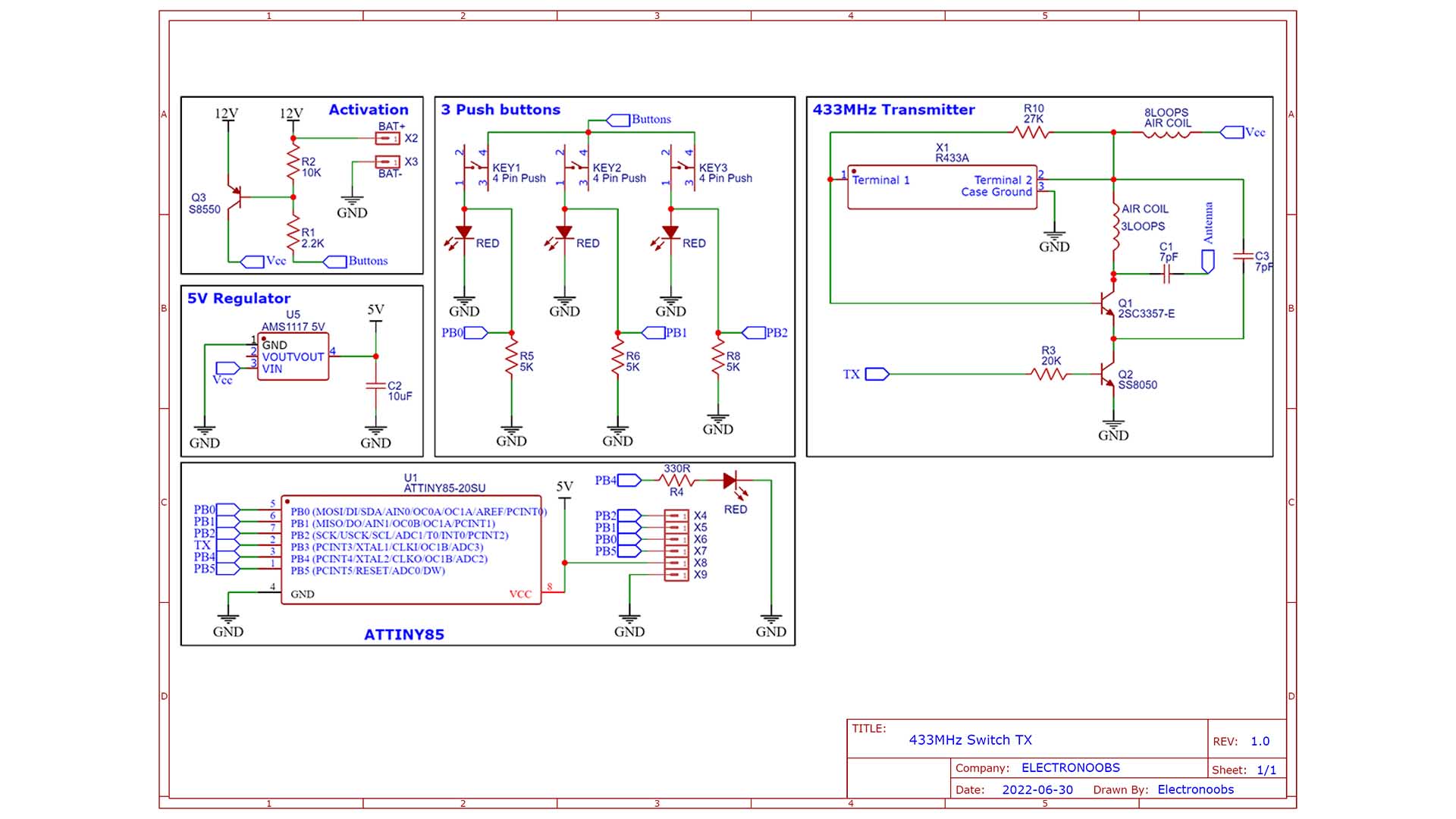
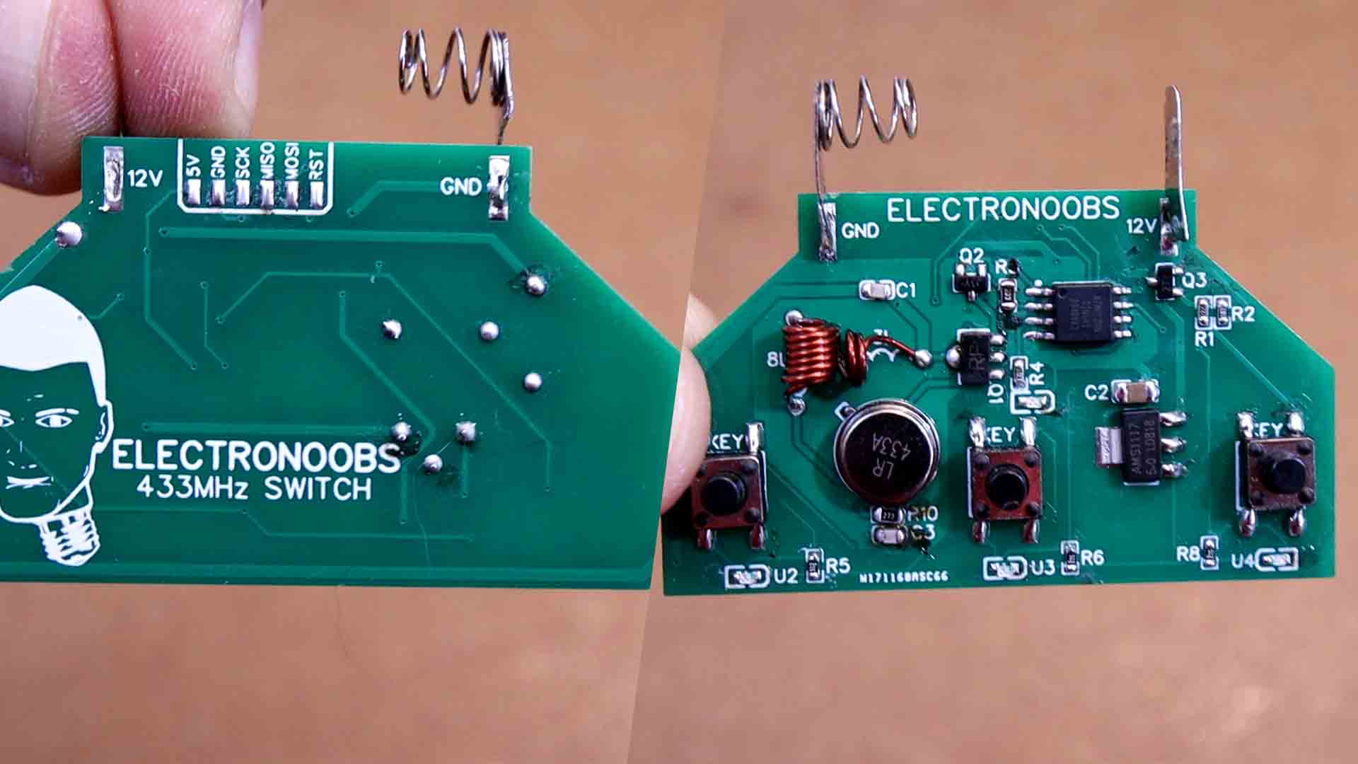
This PCB has to be small so it will fit inside a regular size light switch for which I’ve designed and printed this case. We will check the case later with more details. My PCB is only 60mm wide. Ok, so the PCB has the push buttons part, the activation part with the BJT transistor, the 5V regulation part for the microcontroller, the microcontroller itself which in this case will be an ATtiny 85 and finally, we have the radio transmitter.
This transmitter part is based on a cheap radio transmitters that work with a 433MHz crystal. Later we will some sort of modulation together with this 433MHz crystal to send the data. To program the ATTiny, we use the ISP connection and on the back of the PCB we have the ISP pins.
So, get the GERBER files for the PCBs and then go to PCBWAY.com. Click the quote button and insert the data. The PCB amount, the color and so on. In my case I select the green solder mask and save to cart. On the next page, upload the GERBER files you’ve downloaded from my website and place the order. The PCBs from PCBWAY should arrive in a few days. They look great as always.
This is the transmitter code and you could download it from below. Each time we press a button, we detect which button was pressed and send a different code depending on the pressed button. To simulate a serial communication I define the delay time in microseconds for a long pulse, a short one and a sync pulse. I wanted to use the ASK library as I did for other radio based projects, but is not compatible with the ATTiny. Each time I press one of the push buttons, I send a different series of 3 bytes to simulate some sort of secret message. To send the data, if the bit of the data I want to send is a 0, I create a short pulse and if the bit is a 1, I create a long pulse. Each data is followed by a stop bit.
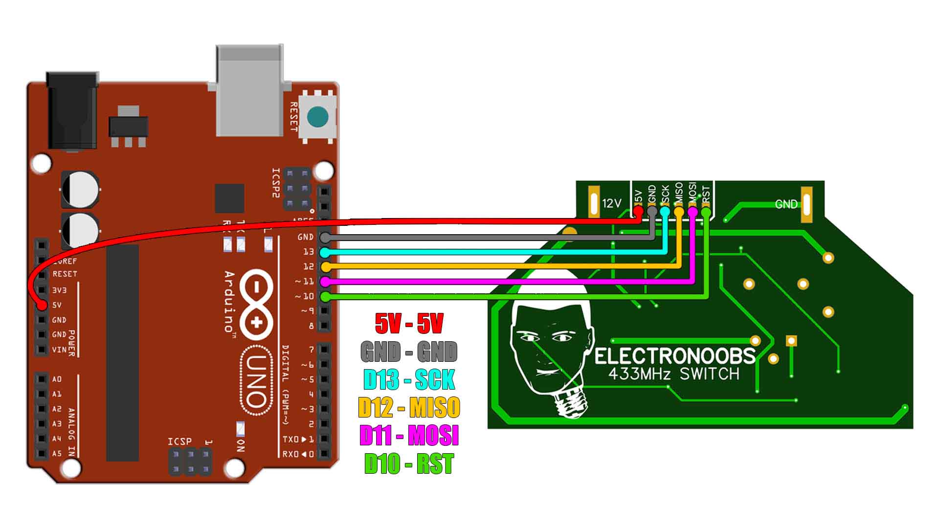
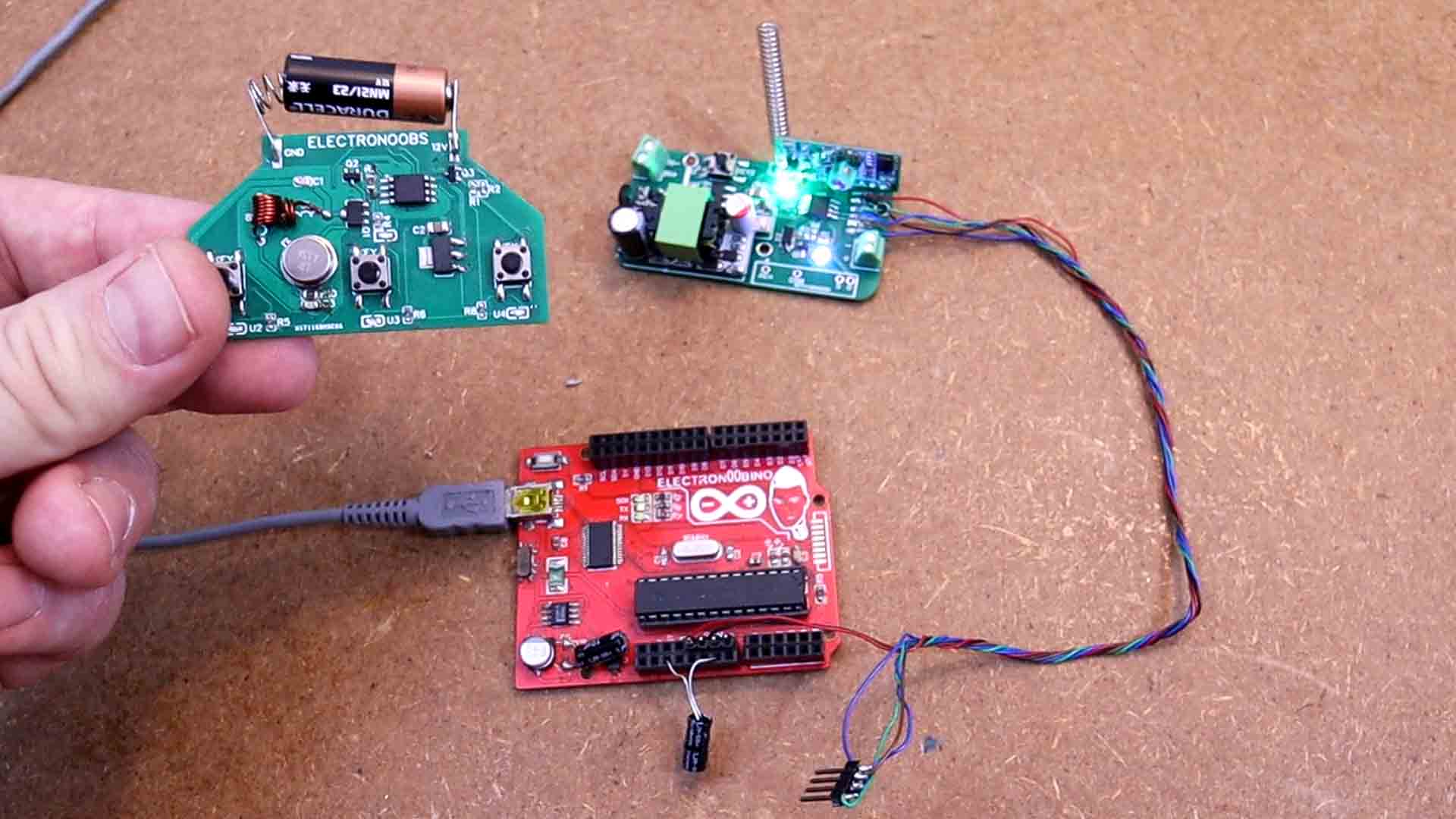
To upload it to the PCB this is what you have to do. Get an Arduino UNO and connect it to your PC. Open Arduino IDE, go to files, examples, Arduino as ISP and open taht example file. Upload that "Arduino ISP" code to the Arduino UNO.
Then, to uplaod the transmitter code to the ATTiny, solder wires on the ISP pads on the back of the PCB. Then connect them to the Arduino on pins 10, 11, 12 and 13 as you can see in the schematic below. In the Arduino IDE, go to preferences. Copy and paste the link below for the external links. Now go to board manager and search for ATTiny. Install those boards. Not go on sketch, board and select ATtiny and make sure you select ATTiny 85. Select the 1MHz internal clock source. As a programmer, select Arduino as ISP since we will use the Arduino UNO as a programmer. Then click the burn bootloader button so the ATTiny will use a 1MHz bootloader (
//Input/Outputs
#define Serial_RF 3               //Pin for the radio transmitter part
#define Button1 2                 //Button 1 pin
#define Button2 1                 //Button 2 pin
#define Button3 0                 //Button 3 pin
#define LED_Pin 4                 //Button 3 pin

//Variables used in the code
#define DelayShort 188
#define DelayLong 564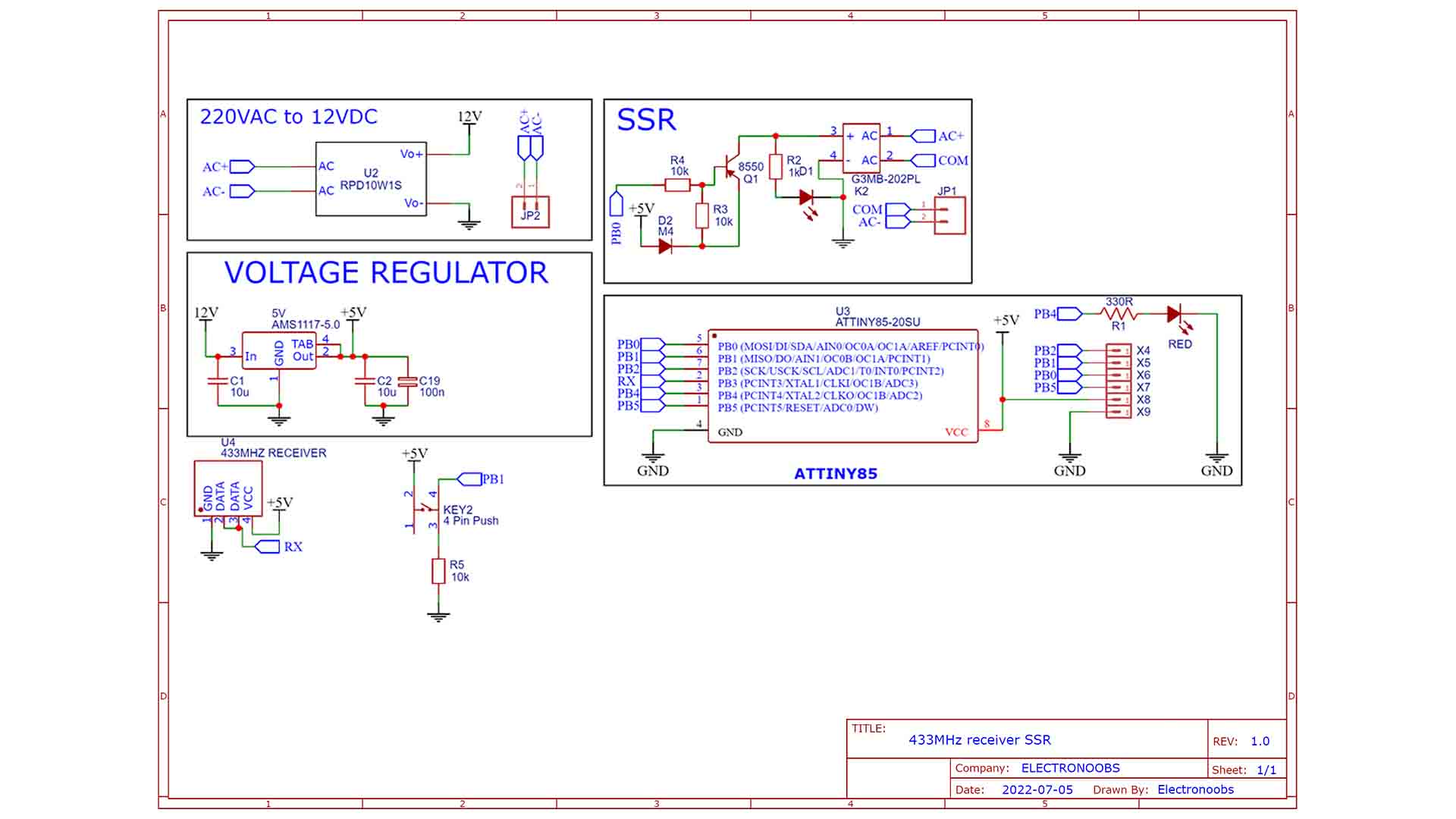
#define DelaySync 5640The reciever schematic is simple. First we get 12V from 220V AC using the small transformer module. I use a 12V mdoule and not directlya 5V one, because we need steady voltage for the ATTiny, and the transformer module has a lot of noise. Instead, we use a 12V one and then we add a 5V LDO which has very steady output. So, we receive data from the radio receiver module with the ATTiny. Decide if the received data is good and turn on and off a PIN connected to the SSR circuit. This circuit with a small BJT, will activate or deactivathe the SSR and that's it. We also turn on and off an LED.
Again, get the GERBER files from the part list above, and then go to PCBWAY.com. Click the quote button and insert the data. The PCB amount, the color and so on. In my case I select the green solder mask and save to cart. On the next page, upload the GERBER files you’ve downloaded from my website and place the order. The PCBs from PCBWAY should arrive in a few days. They look great as always.
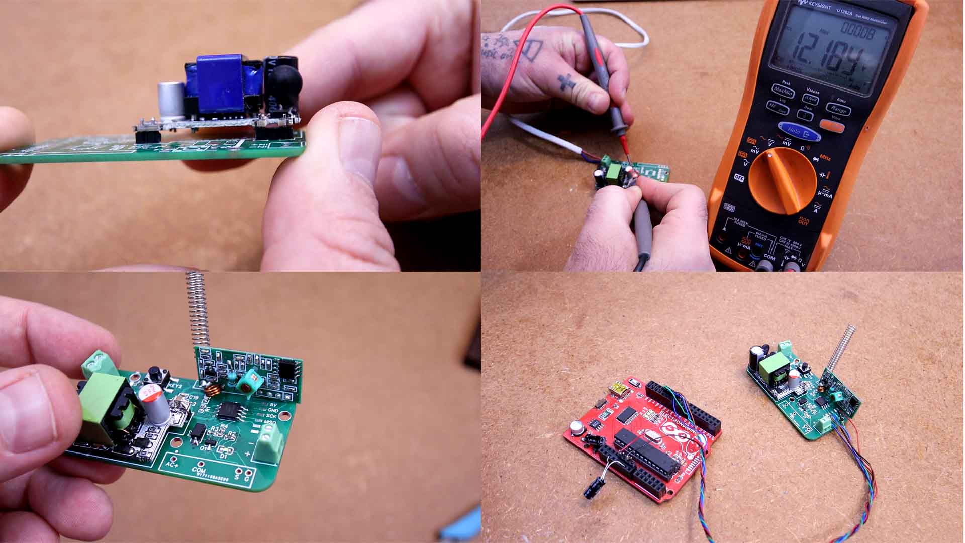
I first solder 4 male pins for the voltage transformer. Then I palace it over and solder it so it will have some clearance from the PCB. I also add the input and output connectors. I supply the PCB at 220V AC and test the output and if it is 12V we can solder the rest. I add the 5V regulator, the ATTiny, and the small resistors, diodes and capacitors. I solder the radio receiver in palace. I will solder the SSR once I test if the code works or not on the PCB as well. So just like that, the receiver PCB is ready.
So, again, solder wires to the ISP pads on the receiver PCB. Then connect the pins to the Arduino UNO with the ISP code. Download from below and open the receiver code. This will use something like the "pulse in" function and measure the length of the pulse and again, if it is short it represents a 0 and if it is long, it represents a 1. Then, we check the receive data and if we detect the secret code we've sent in the transmitter code, we turn on and off the relay. That’s it. Remember to make the same step as before with the Arduino UNO as ISP and burn the 1MHz bootloader for the ATTiny86. Then again, select the ATTiny board and 1MHz internal clock and upload the code to the receiver board.
//Inputs/Outputs
#define Pulse_In 3              // Pin from the radio receiver part
#define RX_LED 4                // An LED connected on pin 4 for warning messages
#define SSR 0                   // The SSR relay circuit is connected on this pin
#define Msg_Length 3            // Defined message length for specific transmitter


// All times in microseconds
#define Min_Gap_Time 5000       // nominal = 5600
#define Max_Gap_Time 6200       // nominal = 5600
#define One_Bit_Time 120        // nominal = 188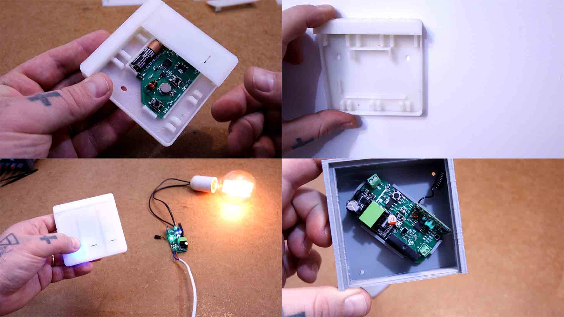
#define Zero_Bit_Time 500 // nominal = 564Get the STL files from below. The transmitter has a base case that will get screwed on a wall. Then you can add 3 buttons on top that will push the buttons on the PCB. use translucent PLA if you want to see the light through the plastic. The receiver case has the shape of the PCB and it can also be screwed on the wall. It has holes for wires input/output.
Now you could test the connection. And it works, the LED turns on and off so that means the SSR would also turn on and off. You can get my PCBs, the code for the transmitter and receiver, the schematic and the part list from above for free and maybe make the same project. Again, be careful working with 220V AC because it is very dangerous and never touch the PCB while it is powered up.
If my videos help you, consider supporting my work on my PATREON or a donation on my PayPal. Thanks again and see you later guys.