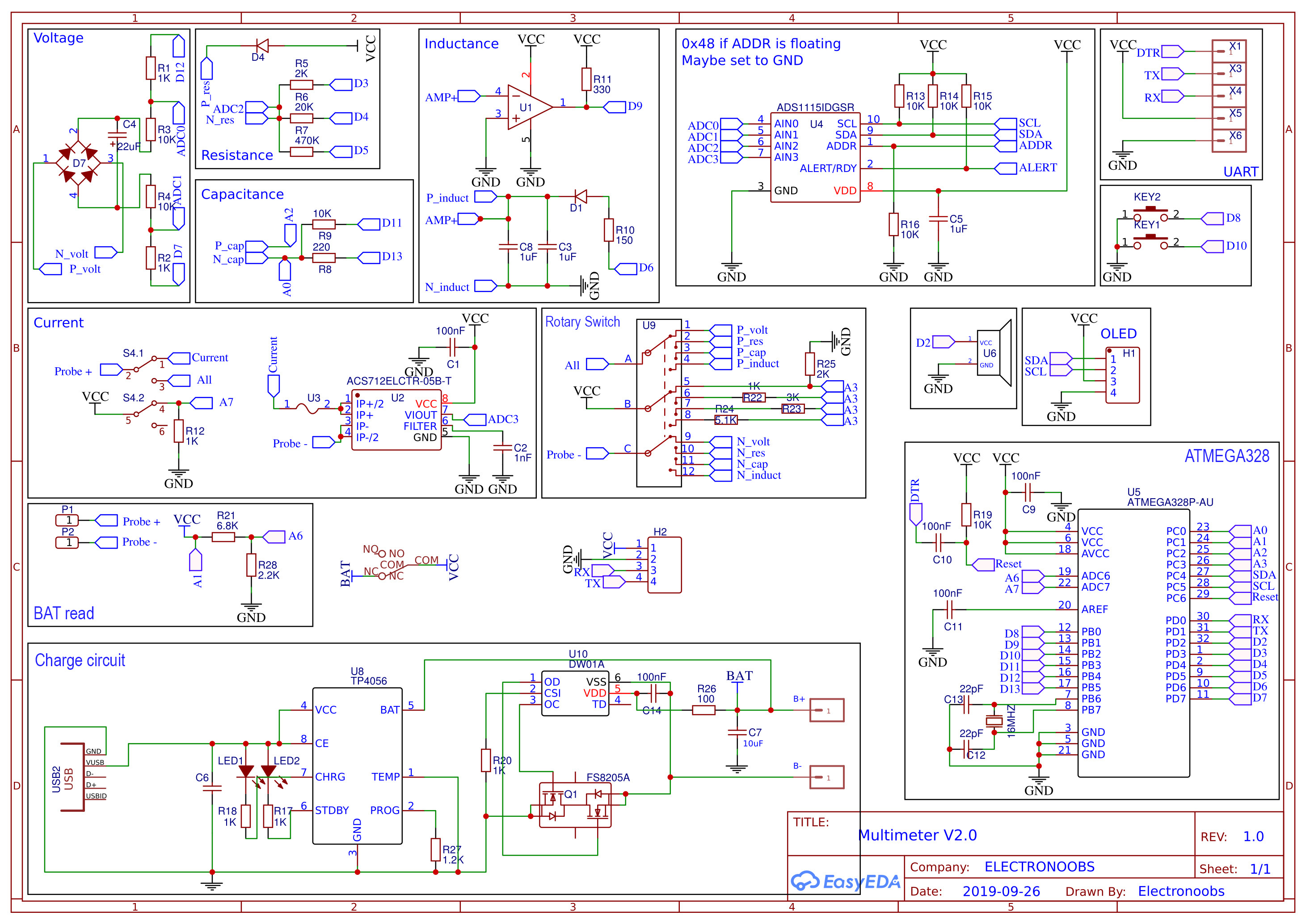
The schematic could be a bit tricky. But I've separated all parts. The first block should be the one in the middle witch is the rotary switch. As you can see the input from the probe is divided into 4 outputs for voltage, resistacne, capacitance and inductance. Current is done separatelly with a sliding switch (S4.1). The first measure block is the voltage one. As you can see we have the input from the probes connected to the full bridge rectifier and then we have a capacitor so we can store the voltage for AC mode. Then, that voltage is connected to some dividers and the output of the dividers to the ADC0 and ADC1 of the ADS1115, so in this way we can measure in differential mode and be able to measure negative voltages too.