


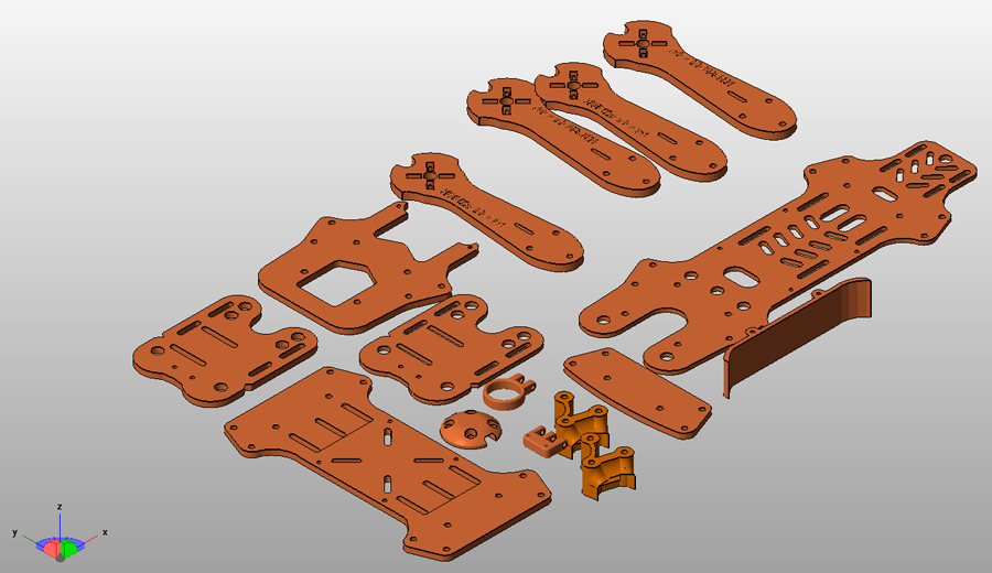
In the photo above we can see al the 3D STL files. Print each of it using 3 perimeters, at least 25% infill and PLA material. The files are already rotated and ready to be printed. Once you have all the parts we can start the assembly. First, using 12 M3 screws join the 4 arms with the bottom board. I won't use the camera and extra parts for this tutorial. All I will use are the bottom and top board, the four arms and the 4 wire separators. So as I said, join the four arms but don't screw them in place yet. Before you screw everything you first have to put in place the brushless motors and the ESCs. Screew in place with 4 screws each motor on each arm. Be carefoul, there should be two clockwise and two counterclockwise motors. Make sure whitch is whitch and screw them in place. Use the next diagram to place the motors.

To make the difference between the motors just check in witch way the propeller screw close. It always has to be in the oposite direction as the motor turns. Now that you have screwed each motor in plce is time to add the ESCs. You can see that each ESC has 3 wires. The ESC middle wire always goes to the middle wire of the motor. But the other tow will decide the spin way of the motor.
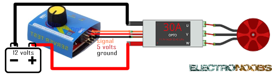
So here is what i recommend you to do. First buy a cheap pwm generator module like this one. This so called servo tester will send a PWM signal that will make the motor to spin, just as a flight controller of a drone would do. First solder and isolate using shrink tube the middle wire of the motor to the middle wire of the esc witch usually is black. Now solder the other two, red and yellow, but don't isolate them yet. Connect the servo tester to the ESC pins, ground, 5 volts and signal like in the schematic below. Now put the tester in the low position and connect 12 volts to the ESC. After the confirm sound increse the signal of the servo tester and write down the spin direction. If it's ok isolate the two wires. If not, switch the two wires between them and isolate with shrink tube.
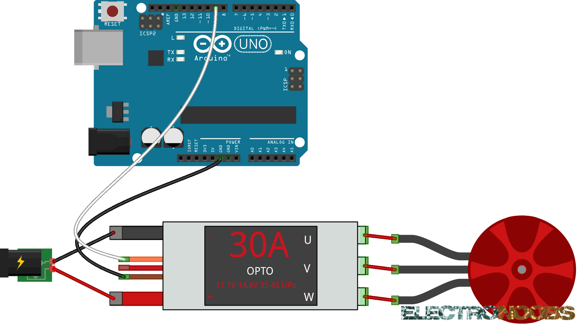
If you don't want to buy a servo tester just hook up an arduino as in the next schematic and uplaod the next code to it. This code will send a PWM signal to the ESC. Usually the min period of the PWM signal used for ESCs is 700us or 1000us and the maximum is 2000us. Upload the code and open serial monitor. Don't connect the 12 volts battery yet to the ESC. Any ESC needs a minimum pwm signal to start up before connecting the battery.
/*ESC calibration sketch; author: ELECTRONOOBS */
#include <Servo.h>

#define MAX_SIGNAL 2000
#define MIN_SIGNAL 1000
#define MOTOR_PIN 9
int DELAY = 1000;

Servo motor;

void setup() {
  Serial.begin(9600);
  Serial.println("Don't forget to subscribe!");
  Serial.println("ELECTRONOOBS ESC calibration...");
  Serial.println(" ");
  delay(1500);
  Serial.println("Program begin...");
  delay(1000);
  Serial.println("This program will start the ESC.");

  motor.attach(MOTOR_PIN);

  Serial.print("Now writing maximum output: (");Serial.print(MAX_SIGNAL);Serial.print(" us in this case)");Serial.print("\n");
  Serial.println("Turn on power source, then wait 2 seconds and press any key.");
  motor.writeMicroseconds(MAX_SIGNAL);

  // Wait for input
  while (!Serial.available());
  Serial.read();

  // Send min output
  Serial.println("\n");
  Serial.println("\n");
  Serial.print("Sending minimum output: (");Serial.print(MIN_SIGNAL);Serial.print(" us in this case)");Serial.print("\n");
  motor.writeMicroseconds(MIN_SIGNAL);
  Serial.println("The ESC is calibrated");
  Serial.println("----");
  Serial.println("Now, type a values between 1000 and 2000 and press enter");
  Serial.println("and the motor will start rotating.");
  Serial.println("Send 1000 to stop the motor and 2000 for full throttle");

}

void loop() {

  if (Serial.available() > 0)
  {
    int DELAY = Serial.parseInt();
    if (DELAY > 999)
    {

      motor.writeMicroseconds(DELAY);
      float SPEED = (DELAY-1000)/10;
      Serial.print("\n");
      Serial.println("Motor speed:"); Serial.print("  "); Serial.print(SPEED); Serial.print("%");
    }
  }
}
Now that you've upload the code open the serial monitor and follow the instruction. The code will first send the maximum speed. That wil put the esc in configuration mode. Connect the battery (or power supply) to the ESC and waid 2 seconds. After two seconds type enter and the ESC is calibrated. Now send a valuse between 700 and 2000 to start the motor. 700 is motor stop and 2000 is full throttle.
Now that you are sure that each motor is in the correct position solder all the wires and isolate them. Cut the wires if to long
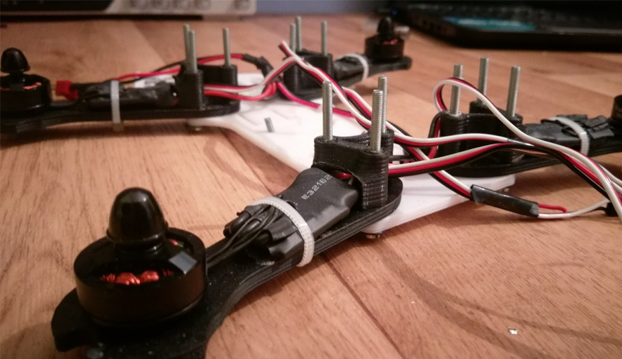
Finally, solder a high current wire to each input of the ESCs. Use black for ground and red for 11.1 volts. Join together all 4 red wires and all 4 black ones. Add a male lipo connector to those wires.
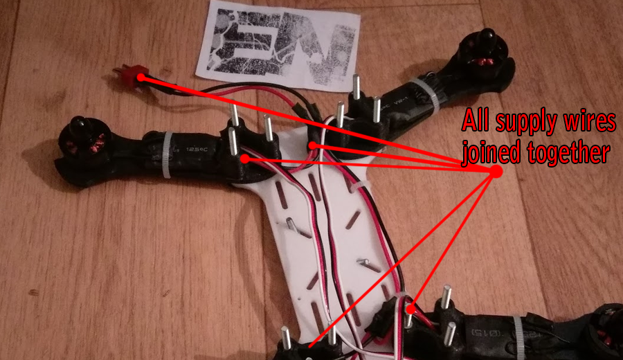
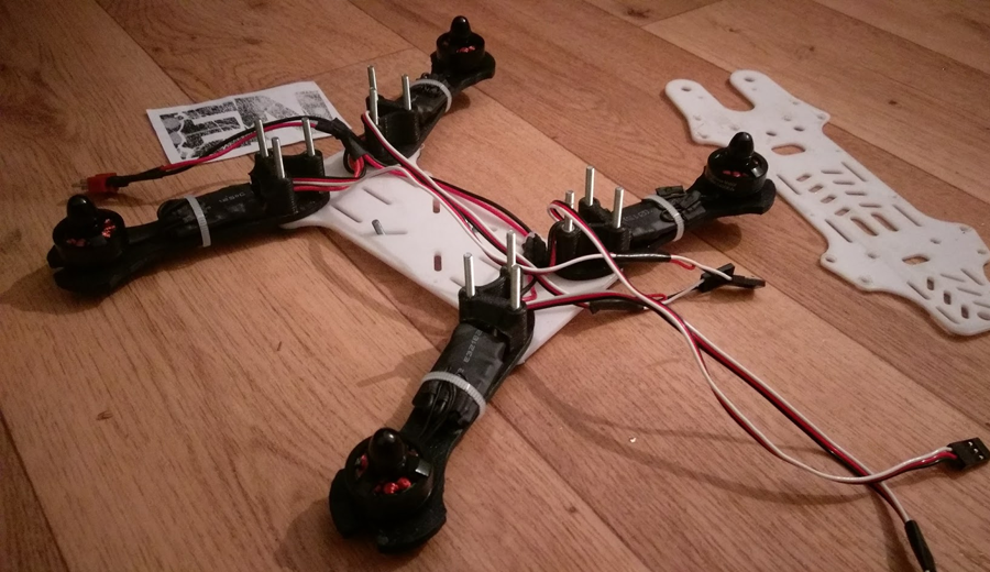
This is the complete body. We have each arm with one ESC and one motor. All ESCs are connected to the male lipo connector. In the middle we will put the flight controller. Don't close the top plate yet. Leave it like this till all the electronics are ready.