About me
  History
  Let's learn
  Contact us
  Arduino tutorials
 Circuits tutorials
  Robotics tutorials
 Q&A
Q&A Blog
Blog  Arduino
  Circuits
 Robotics
  Modules
  Gadgets
  Printers
  Materials
  3D objects
  3D edit
  Donate
  Reviews
  Advertising


Mini oscilloscope DS203 - Page 1
This is an amazing product. It’s a mini DSO that you could fit in your pocket. Rather you don’t have the money for a fully equipped DSO like this one or you often work outside your lab, this portable oscilloscope would be perfect for you. In this review, we will take a look at its main characteristics and put it to the test. So, let’s get started.
Let's start
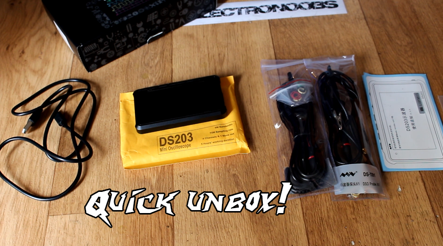
Today we are going to take a look at this mini DSO from e design, the DS two hundred and 3. Inside of the received box we first have the oscilloscope and a USB cable. On the next level we have two probes, a small safety instruction manual and one hexagonal screwdriver, probably to open the case of the oscilloscope if we want. Ok, that’s it with the unboxing, quite quick. Now let’s take a look at the oscilloscope.
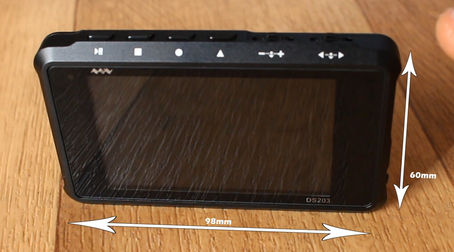
It has a very nice look with an aluminum case. Its dimensions are of 98 mm long by 60 mm height. The screen dough, has a diagonal of 7.8 cm and it’s a colored display. On the top, we have the control buttons and on the sides, the on and off button, the probe inputs and outputs and a USB connector. It has 2 analog, and 2 digital channels but it only comes with these two probes. The probes don’t have BCN connector like a normal oscilloscope so if you want to have 4 of them you should probably buy separately the probes with IPS connector. The probes have no trimming control but there might be an inside adjustment knob. We will see that later.
To navigate through the menu, use the first right sliding button. The first thing I will do is to turn off all the channels except the first blue one. For that I press downwards the second sliding button and I’ll go up one level on the menu. Here I select all the other channels and set them to off. Now all I have is the blue channel which is channel A. Have in mind that if an indicator is blue, it will show information about the blue channel, if it is yellow about the yellow one and so on. If you want this configuration any time you start your oscilloscope just go at the bottom of the vertical menu, select SAVE and press downwards the left sliding button. My configuration is now saved. I reboot the device but my configuration is still selected.
Ok, I connect the probe to the channel A and apply a square wave to it using the signal generator of my main oscilloscope. I select a scale of 0.5 volt per square and by going to the vertical menu I place the trigger level in order to see the signal. The square signal that I apply it’s a 2V peak to peak one of 20Khz. Now if I press the circle button on the mini oscilloscope, I could see some measurements. To select the measured channel just long press the circle button. Here you could select the channel or the type of measurement. Use the right slide button to go up or down.
The left slide button to select the measurement type. And by pressing downwards the left slide button select the channel. I select channel A for all of the measurements. I add a peak to peak, frequency, and the RMS measurements. Now, press downwards the right slide button to exit the menu and press once again the circle button. There you go, I’ve got the measured frequency of 20kHz and a peak to peak of around 2 volts. I have a small error for the peak to peak value which is not perfectly 2V, but that could be for many reasons and we could even calibrate this if we want.
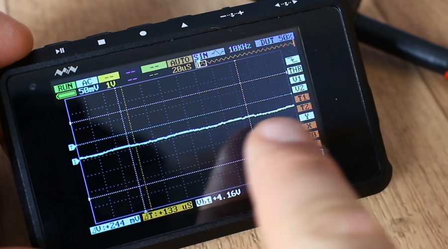
Now let’s make a short analysis. Using the Arduino I will send some signals through the UART port. I connect the probe to the TX pin of the Arduino, connect it to the PC and upload a small sketch that will only write data through the UART port. Now I open the serial monitor and start sending different characters.
I can see on my oscilloscope the data but it is very fast. For that I select single trigger and now, it will stop acquiring at the first falling edge detected as it was configured for a UART transmission. Here is my signal. To zoom in, we go to the time scale selection and we start lowering the value till it zooms in. Now I can analyze the serial signal and obtain the 8 bit value.
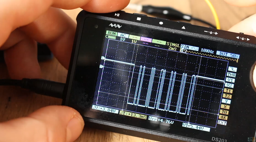
Now let’s test it’s maximum frequency without distortion. At 20KHz, as you can see we have a perfect square wave. I increase the frequency up to one MHz which for basic oscilloscopes is not that high frequency since even the Arduino has a 16MHz quartz clock. The signal is still quite ok but at 2MHz I can start to see that the square wave is not that square any more, and around 4MHz it looks more like a sinusoidal wave.
There’s a logic explination for this. The square wave it is still a sine wave with its own period and frequency. But the square wave has some additional high frequencies in it. The thing is that this device is filtering those high frequencies since it is limited in bandwidth so, finally, all you remain with is some kind of basis sine wave. The specs of this device tells us that it has a sampling rate of 72MS per second and a 8MHz bandwidth but the signals we could observe with no distortion are up to around 3Mhz so have that in mind. For the signals I work with for my arduinos and other electronics, that is more than enough. But you should consider buying a full equipped DSO for more professional and high tech projects.
One more thing this small device has is a signal generator. We could generate square, sine, triangle and saw tooth signals which are the basic signals for any signal generator. I connect the output to my oscilloscope and analyze the square signal first. You could output a signal of up to 8MHz. This is the square wave of 1Mhz and a duty cycle of 50%. Go up to 8MHz, once again it looks more as a sine than a square wave.
Now I change the output signal to a sine wave and this is what I get and the maximum frequency is limited to 20KHz. The reason of this steps is the DAC or digital to analog converter that creates the signal and this is a very bad one. It’s not that fast and it has very bad accuracy. Counting the steps I reach a value of 16 steps which tells me that the DAC has 4 bits which it is quite low.
I’ll connect the output of another signal generator with the same frequency in order to see the differences. Visually the difference is quite clear. But lets take a look at the frequency spectrum of this signals. The spectrum of the sine wave created with my signal generator has only one frequency component on the spectrum. Now for the one created with the small DSO we can see the main frequency and a bunch of other one with smaller amoplitudes.
Another cool thing is the ability to save BMP captures of the screen and also CSV files compatible with excel. For that, trigger your signal first and press the square button. Here you could select save BMP or save CSV file. I select both. Now I connect the DSO to my PC using the USB cable and open the folder. Here is my capture. Quite nice, right? This could be useful while documenting your project.
Now for the digital channels, which are C and D there is no trigger and even if I apply a sine wave, since it is a digital input it will detect only zeros and ones represented by a high or a low pulse. In this case when the sine wave will pass a certain threshold value it will create a positive pulse on the digital channel as we can see here with the green line. The real signal is the one on the analog A channel. So only use this channels for digital signals.
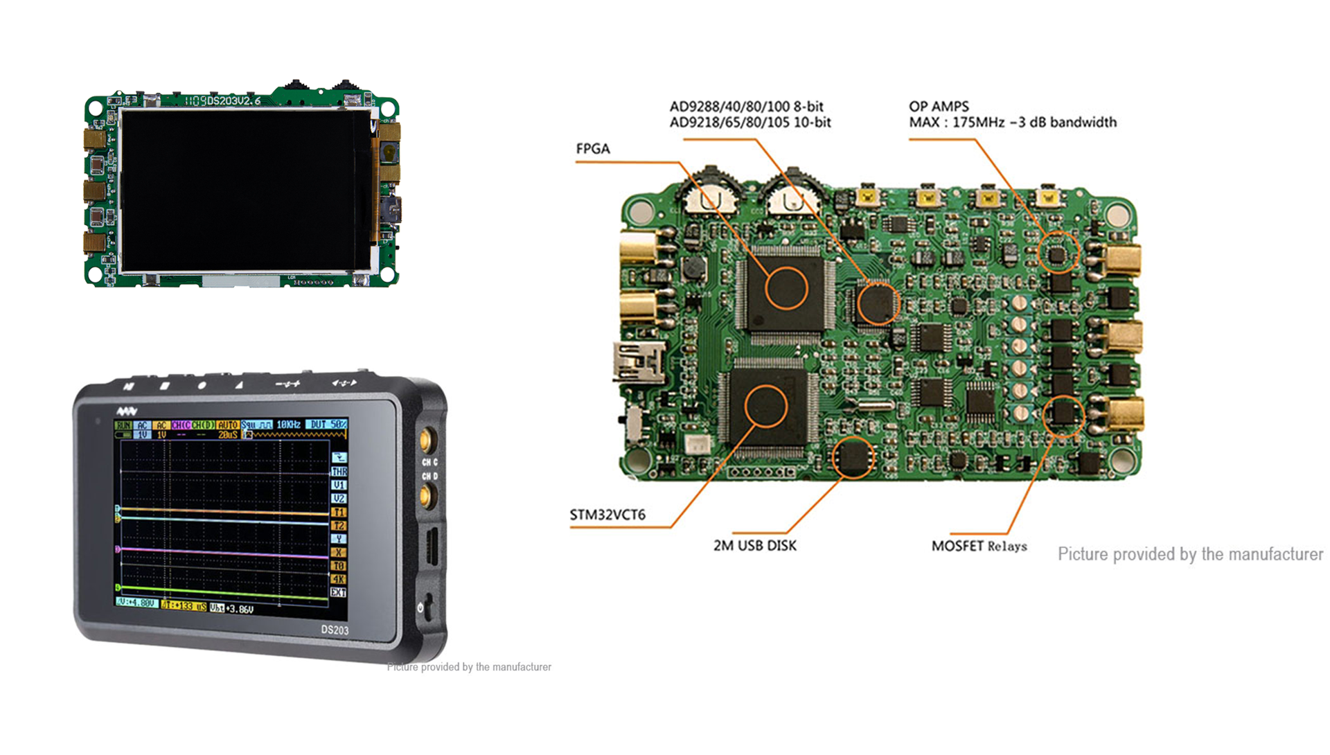
I opened the case by unscrewing just the 4 back screws. Inside we have a LiOn battery of 3.7 volts and a capacity of one thousand mAh. I’ve tested this device around for hours while recording the video and the battery never passed its half value. To charge it just plug the USB to any PC. Here we have the calibration knobs for the probes. I won’t touch this since my signal seams quite good. I won’t go farther so I’ll close back the case. We could see a better view of its components in this photo that you could find in a link below.