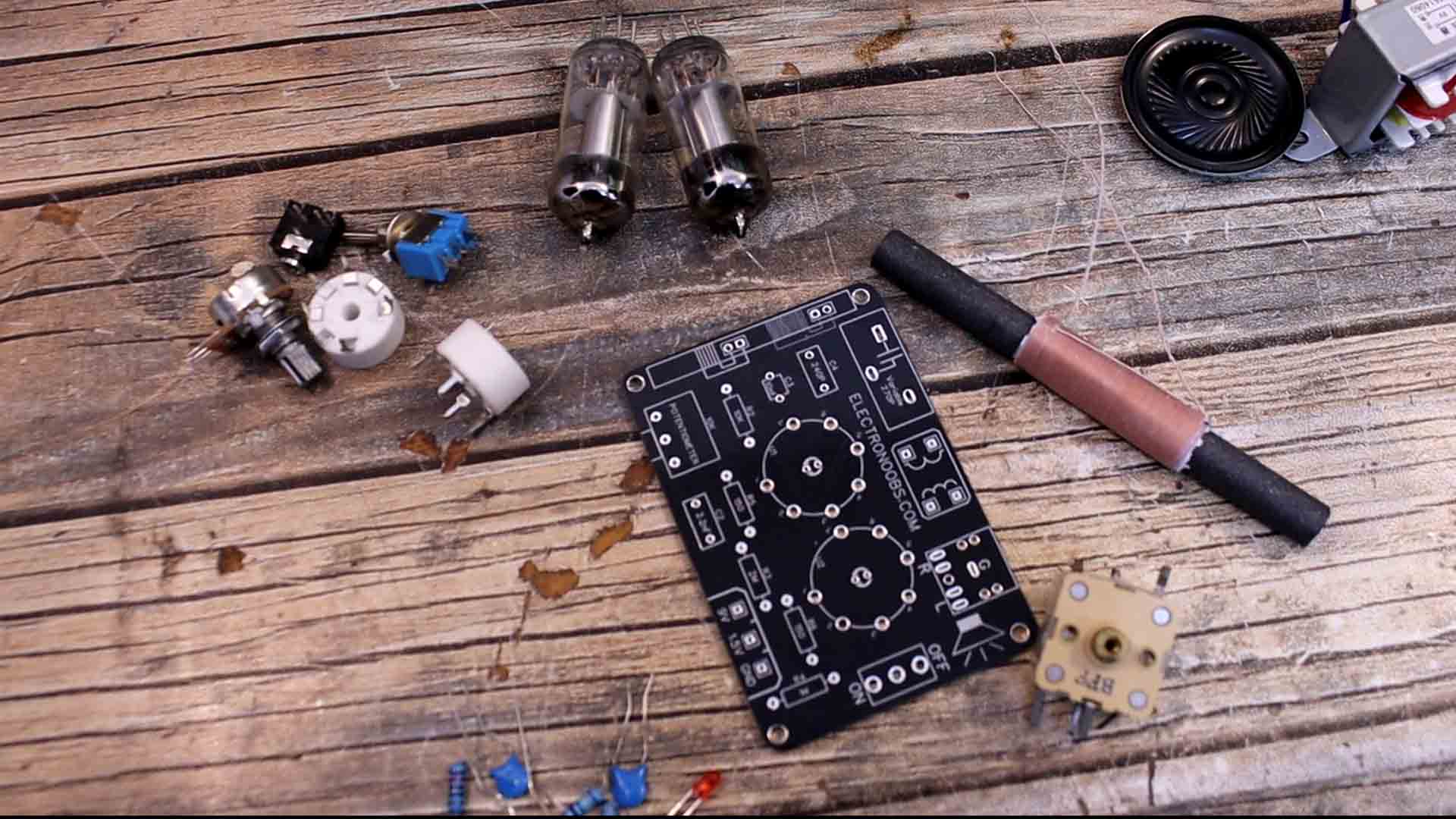
On the next chapter you cn download the PCB GERBER files and order it. Once you receive your boards, get together all the needed components. For the variable capacitor I bought a generic one but I’m not sure which pins I should use. It has 9 pins but we only need 2. We need to find two pins with a capacitance around 270pF. Using my multimeter, I test the pairs of pins and I found 2 with a capacitance of 300pF. For the regenerative coil I bought a typical one. We’ve seen this type of coil on the teardown of the old black and white TV which also had a radio integrated. This is just a ferrite core cylinder with some copper coils on it. One big coil and a smaller one. To find which is which, just use the multimeter in resistance mode and the small coil should have a lower resistance. The rest are just passive components such as resistors, capacitors, a switch and potentiometers. We also need this jack connector for the audio output. And for amplification we need a small transformer with a ratio for 220V to 6V. For the tubes is better to use sockets than soldering them directly to the PCB. So we need two of these sockets and of course the tubes, which are 2P2. For supply we could use a 1.5 and a 9V batteries. But to be sure, I might use my power supply for the tests. That’s all we need, let’s assemble it.