This here is a super high voltage magic wand that I’ve made. If you’re asking why, well, months back I’ve received an email from the VSAUCE3 YouTube channel for a cooperation video on the Harry Potter episode. But since I live in Spain and their office is on the other side of the world, our online meetings were impossible to make during working hours, so we never made that cooperation. Actually, ELECTROBOOM YouTube channel got to make such a project for them and I’ll place a link HERE. But since I’ve already ordered all the material, the PCB, the high voltage capacitors and the generator, well, I will make this project as well and maybe teach you something new on the way. What is a voltage multiplier, how to get high voltage with some transformers and what you could do with such a magic wand project. Have in mind this might be a dangerous project so if you’re not sure about something, don’t make it, always use proper tools and never touch the high voltage components. So, let’s get started.
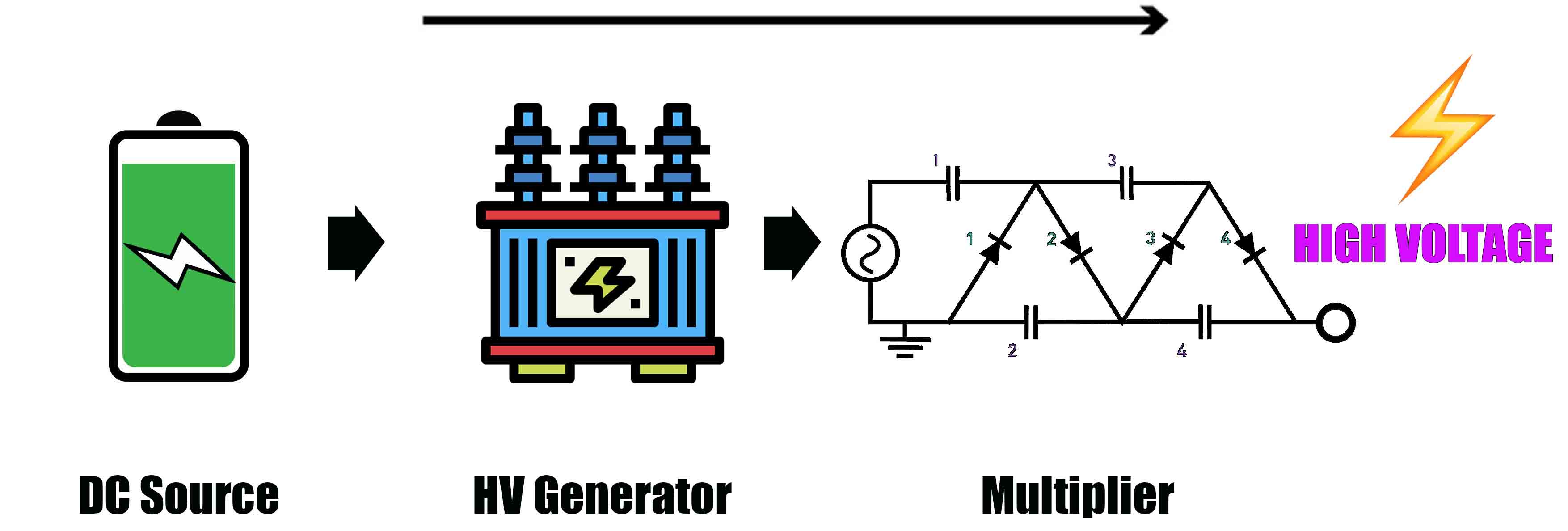
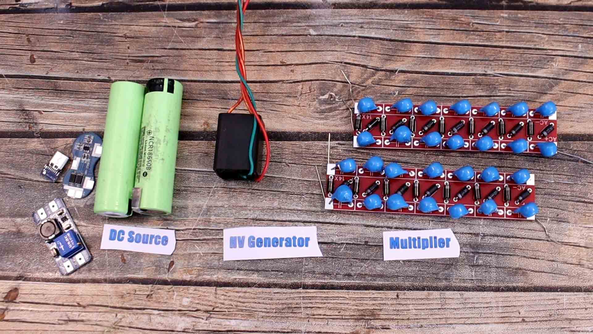
What’s up my friends, welcome back. A magic wand like this one has 3 main parts. The DC supply which can be a normal battery like this one. Then we need to elevate the voltage with some sort of ZVS circuit for high voltage generator. This is usually made with flyback transformers and it creates high frequency high voltage. The third part is the voltage multiplier. For that part I’ve made my own PCB so it would look better and it would be easier to make. The multiplier is using a series of voltage doublers made with diodes and capacitors.
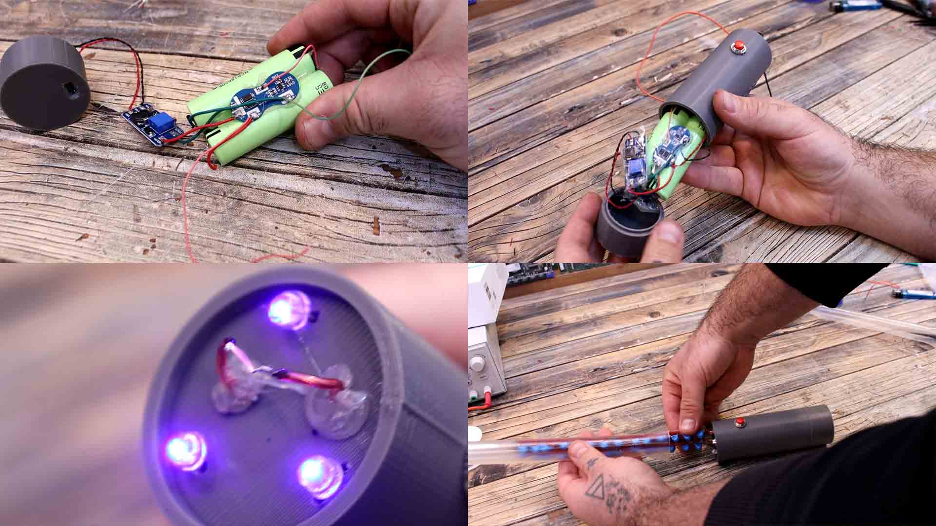
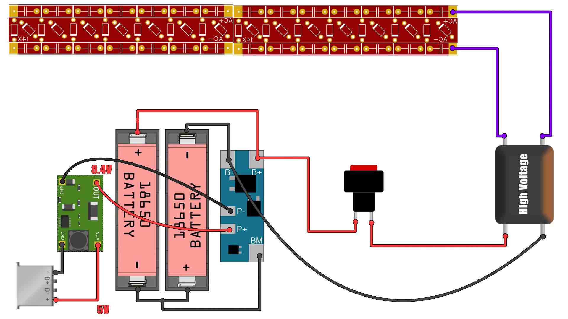
As I’ve told you, for the voltage multiplier I’ve made my own PCB and order it to PCBWAY. If you want the same PCB download the GERBER files from below for free and go to PCBWAY.com and here click the quote now button, select your settings for the thickness, amount of PCBs, color of the solder-mask and save to cart. We need a battery capable of delivering enough current. Together with the batteries we need a charging module so for that I have this 2S BMS charger. We need to connect 8.4V to this module and since I want to charge this with a USB connector I will also add a boost convertor module to rise the voltage from 5V to 8.4V. So we would have a series of the USB cable, USB connector, boost converter, the 2S BMS module and then the battery pack of 2 cells. Ok, so we now have the DC power source. Then we need a HV generator and the multiplier PCB.
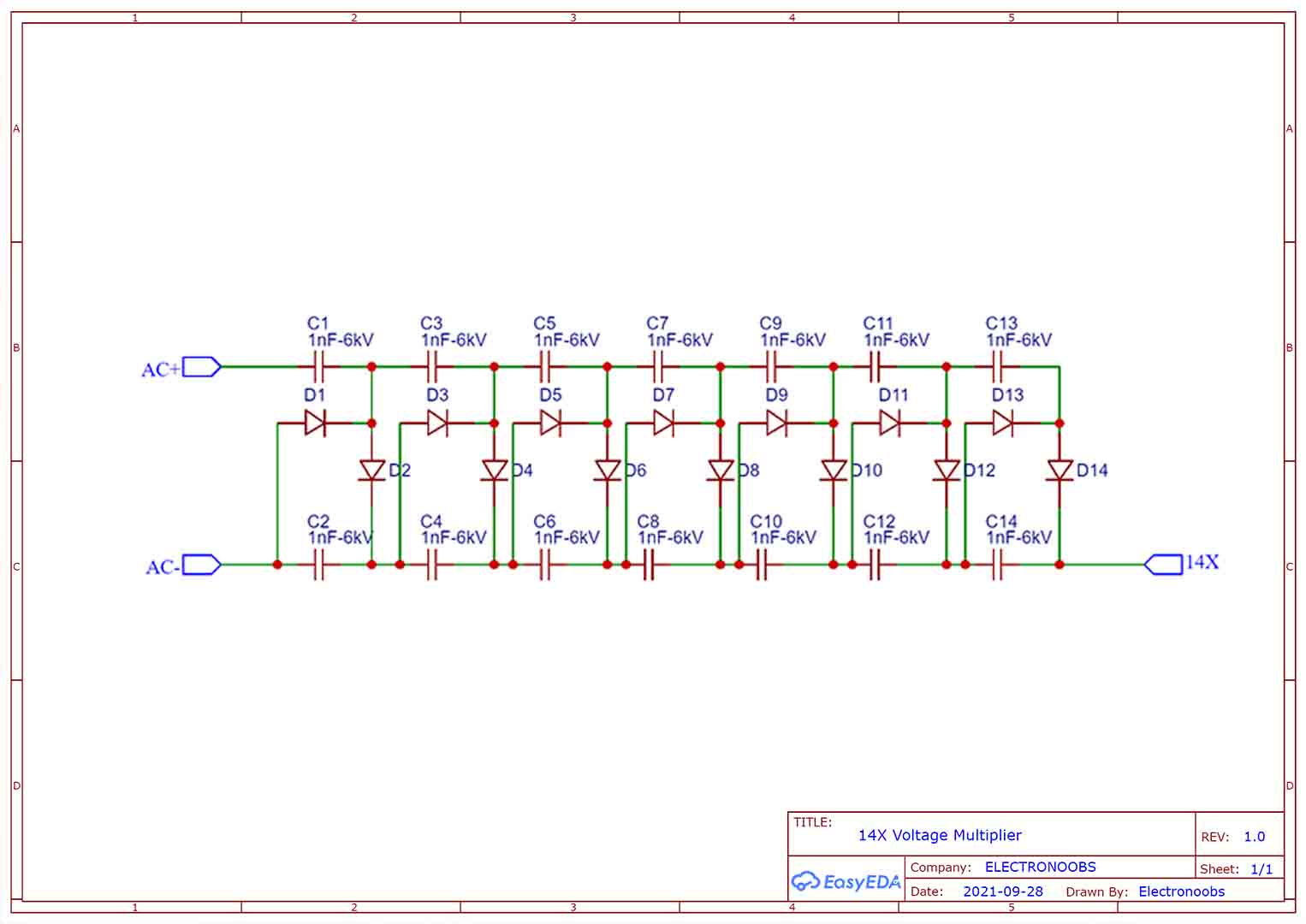
To make the multipliers we need high voltage capacitors and high voltage diodes. These are 15 KV capacitors of 330pF. And these here are 10KV diodes. All we have to do is to follow the silk-layer on the PCB and assemble the multiplier. We add all the capacitors and then all the diodes. Make sure you don’t place the diodes backwards so check the cathode line on the silk layer of the PCB. Just to make sure I’ve made two equal PCBs and I might merge them in series in order to get higher voltage output.
Make the connections as below. The USB connector to the boost converter and set its output to 8.4V. Connect the BMS to the batteries. From the batteries we add a push button and connect it to the HV generator. Add the multiplier at the output and that's it.
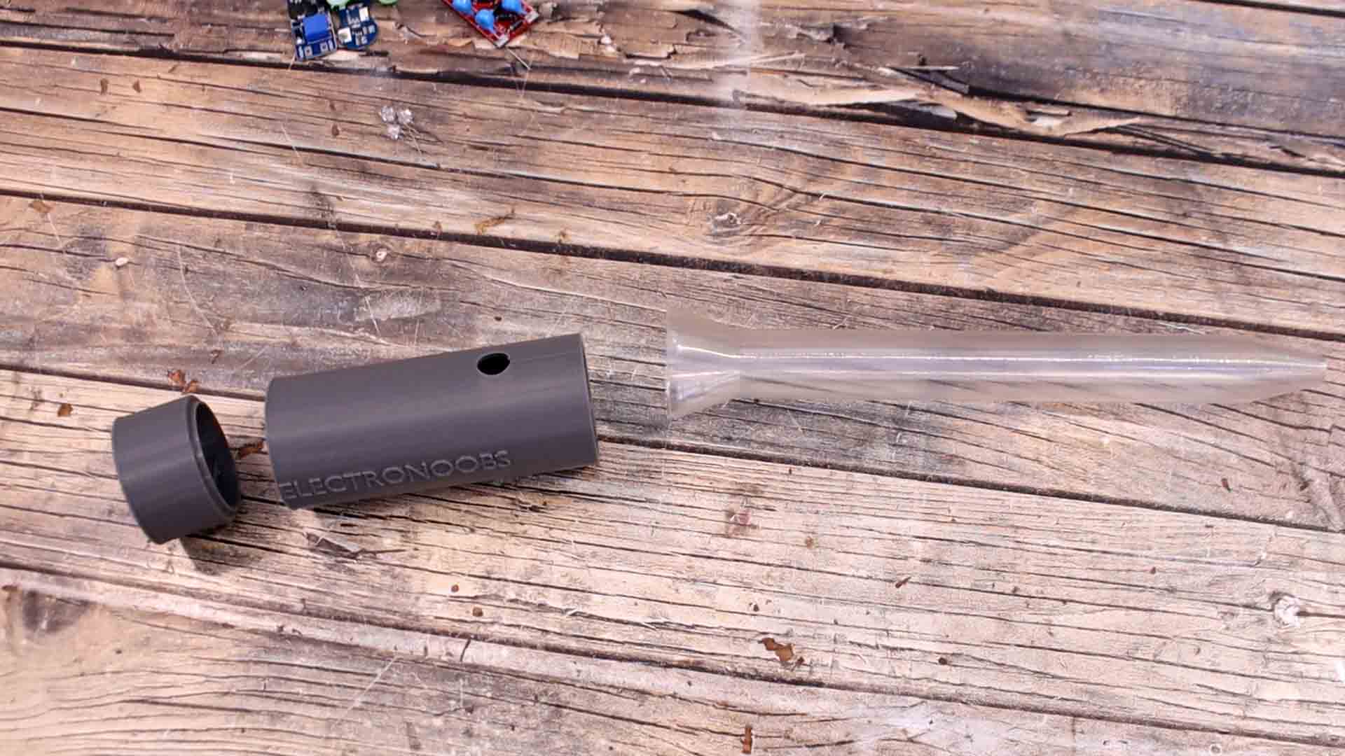
Download the 3D files from below and print them with PLA material. The front part of the wand is printed with transparend PAL from POLYMAKER. When sprayed with alcohool it will turn alost transaprent. Now let's assemble it. The plastic case of the wand is made out of 4 parts. 3 aprts where the circuit will go and 1 part for the multiplier PCBs.
Connect everything as in the schematic. Fit them inside of the bottom case. Then add the multiplier at the output. On top add the transparent part. Then we will fill it with resin so it could be more insulated.
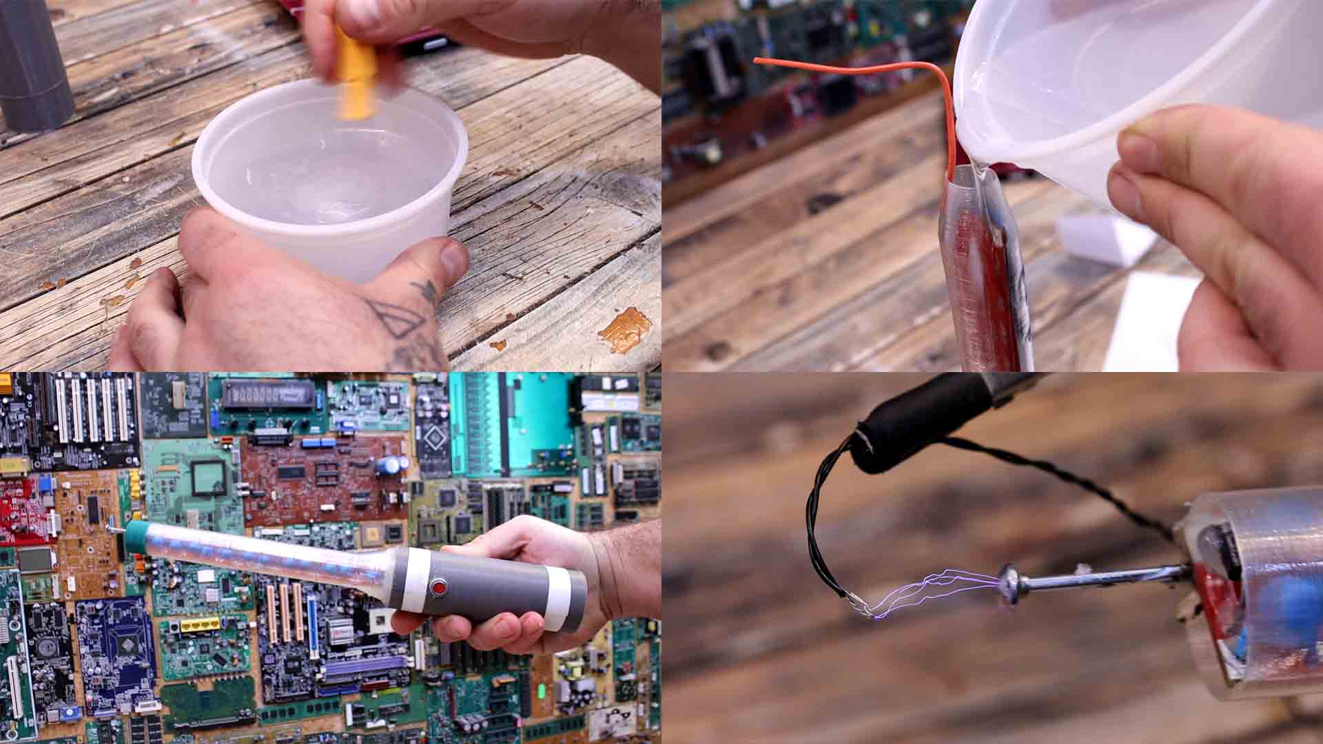
Now that we have it in place, we prepare some resin. I mix 3 parts resin and 1 part activator. Now we fill the entire wand with the resin. The resin I have takes around 3 days to get hard. At the tip I’ve placed a round shaped metal.
You have everything you need to make this project above. My schematic, the part list, my 3D files, the GERBER files for the PCB and a step by step guide. If my videos help you, consider supporting my work on my PATREON or a donation on my PayPal. Thanks again and see you later guys.