Hi guys. This here is my design of a coilgun which is a project I was preparing to make for a long time and I finally made a first version. Before we start, I have to warn you that this is a quite dangerous project for 2 reasons. First, well it fires projectiles at high speed. And second, it works with very high voltage, around 500V so please be careful if you want to make the same project. Use proper tools, stay insulated and never touch the exposed wires while the board is powered on. Also make sure that you fully discharge the huge capacitors each time, because these could store a huge amount of charge. Ok so my design is a bit special and you will see that it is made out of separated PCB for each stage. So if you want more power and more speed, you can just add another stage. Each segment PCB works by its own, having the coil, the capacitor, the power control and the bullet detector so it is very easy to add more stages. So, what do you think? Would this be able to fire through a cardboard box? That sound quite easy, right?. But what about a 4mm plywood sheet? What about some plexiglass? What about some 3mm MDF which is a strong material? Well, stick till the end of the tutorial to find out and by the way, below you can find all that you need to make this same project, such as my schematics, my PCB designs, the part list and so on. So, safety glasses on, and let’s get started.
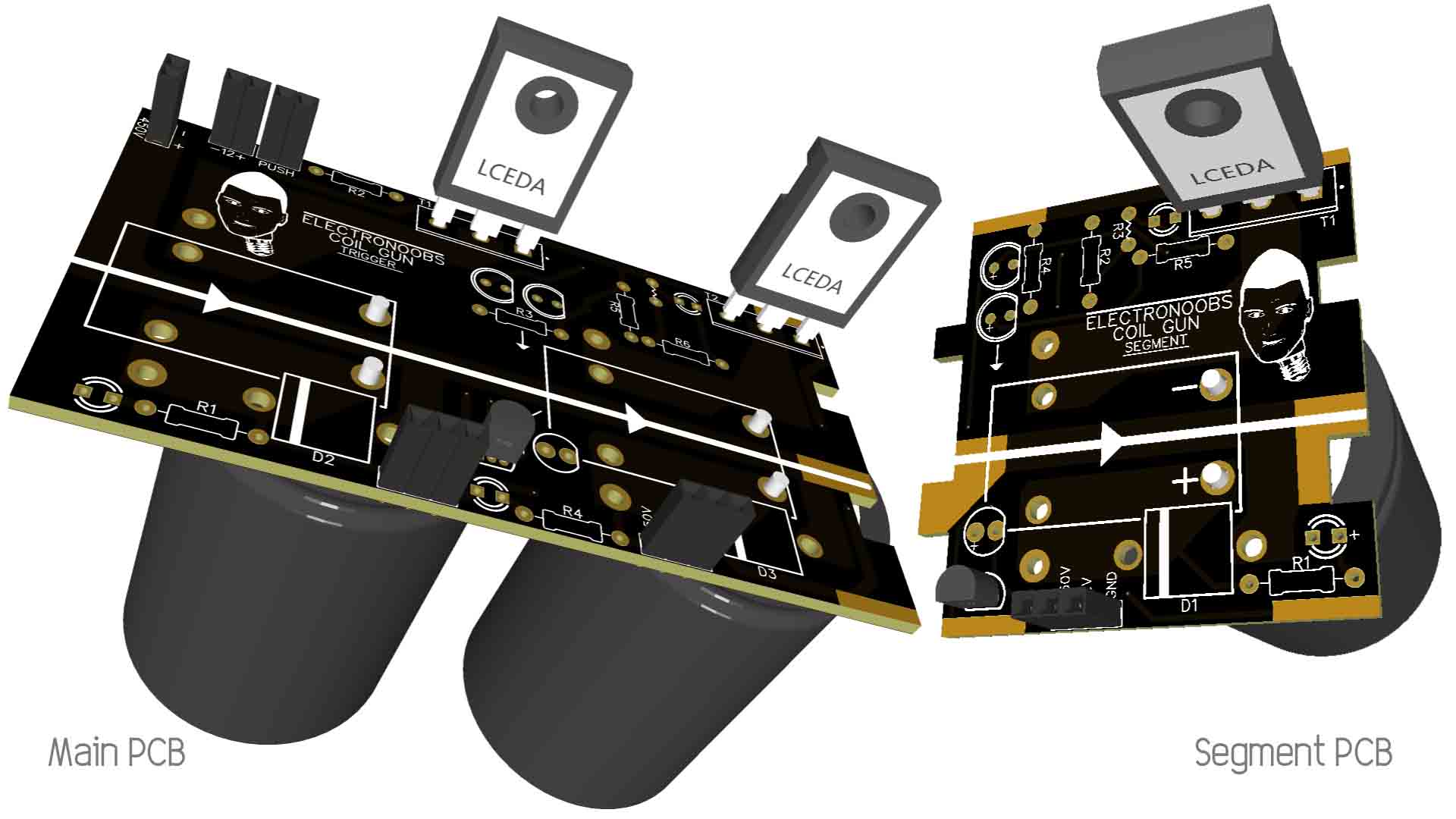
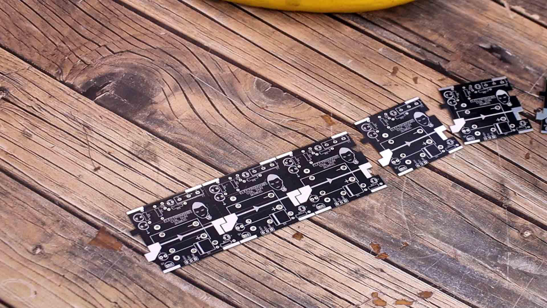
This project is not new, there are a lot of other designs on the internet. As you can see, my design is a bit special and is made out of multiple PCBs. We have this first main board and the rest are merging together to create the gun. The main PCB must be the first stage because it will have the supply connection and the firing push button. And then, all the rest of the PCBs are exactly the same but the more stages we put, more speed will the projectile get. In this way, you can make your coil gun have any amount of stages you want just by adding more PCBs with the same circuit. If you want to make the same project, you can get my GERBER files for both PCBs from below. Then you can go to PCBWAY and order the same boards. Remember you need two files, for the main board and other files for the segment PCB. Each of this coil gun segment can work by its own since it has the detection and power control circuit which is not affected by the rest of the coil gun and we will see how it works in a moment.
A coil gun is based, well, on a coil, obviously. When we apply current to this coil, a magnetic field will be created around it. This magnetic field will attract a metal projectile that we have on one side. The projectile must be ferromagnetic otherwise the magnetic field won’t attract it. But here appears the first problem. The created magnetic field is equal on both sides of the coil, on the left and on the right. So the projectile is attracted from the left side but once it passes the middle of the coil, it will be attracted backwards by the right side magnetic field. So, what the projectile will do is to oscillate till it stops exactly in the middle of the coil. For that we add a detector at the output of the coil and when we detect the bulled getting out, we cut off the magnetic field using a thyristor connected to the coil. We add multiple coils in series for more speed.
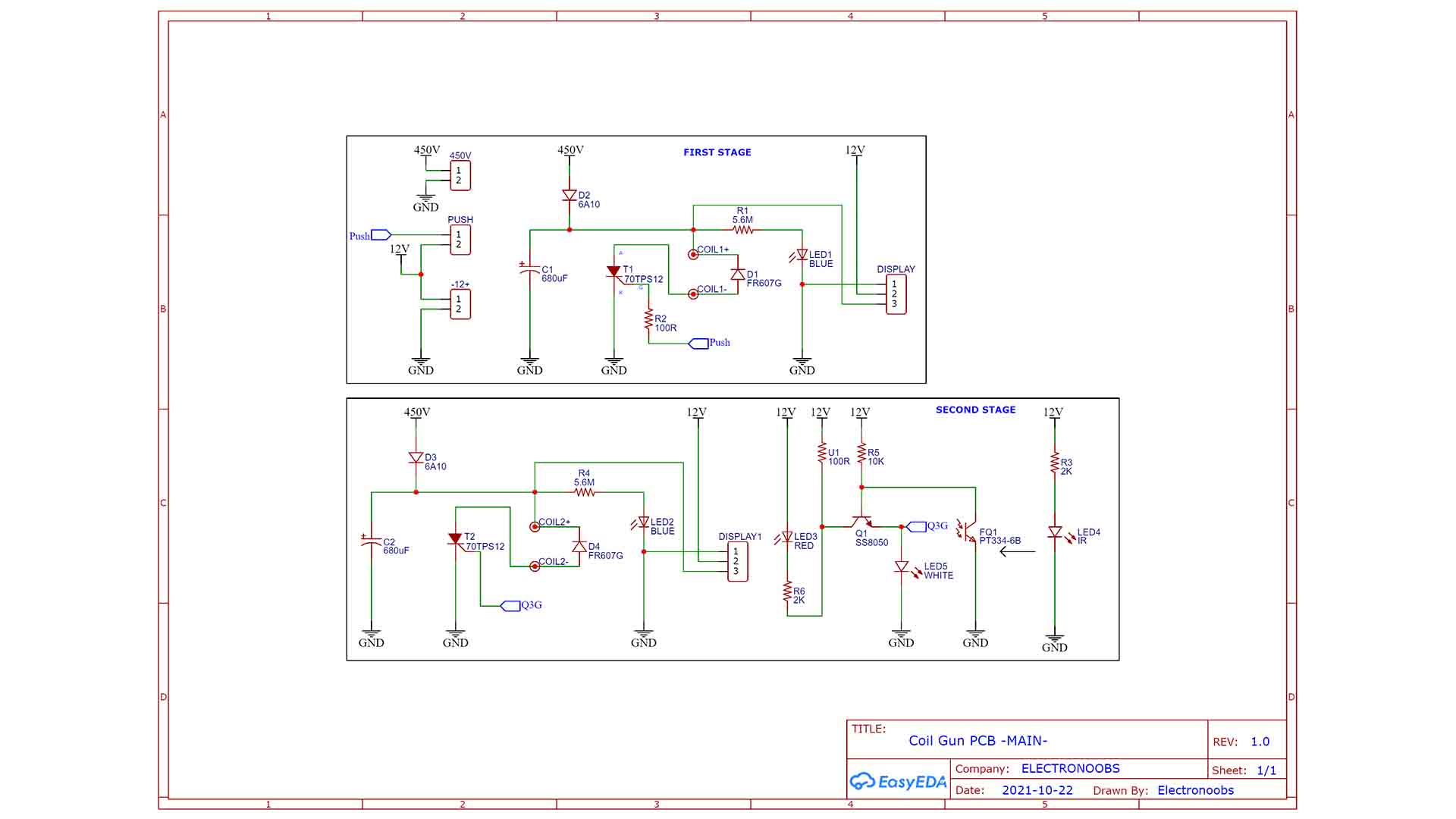
The circuit for this PCB is a bit different from the segment PCB and this below is the schematic. This PCB has two stages and we have the same power control part as for the segment PCB, but the Thyristor is activated with a push button instead of the phototransistor. This PCB also has the input of 450V and 12V from the battery pack. We only need one of this PCB and any amount of the segment PCBs.
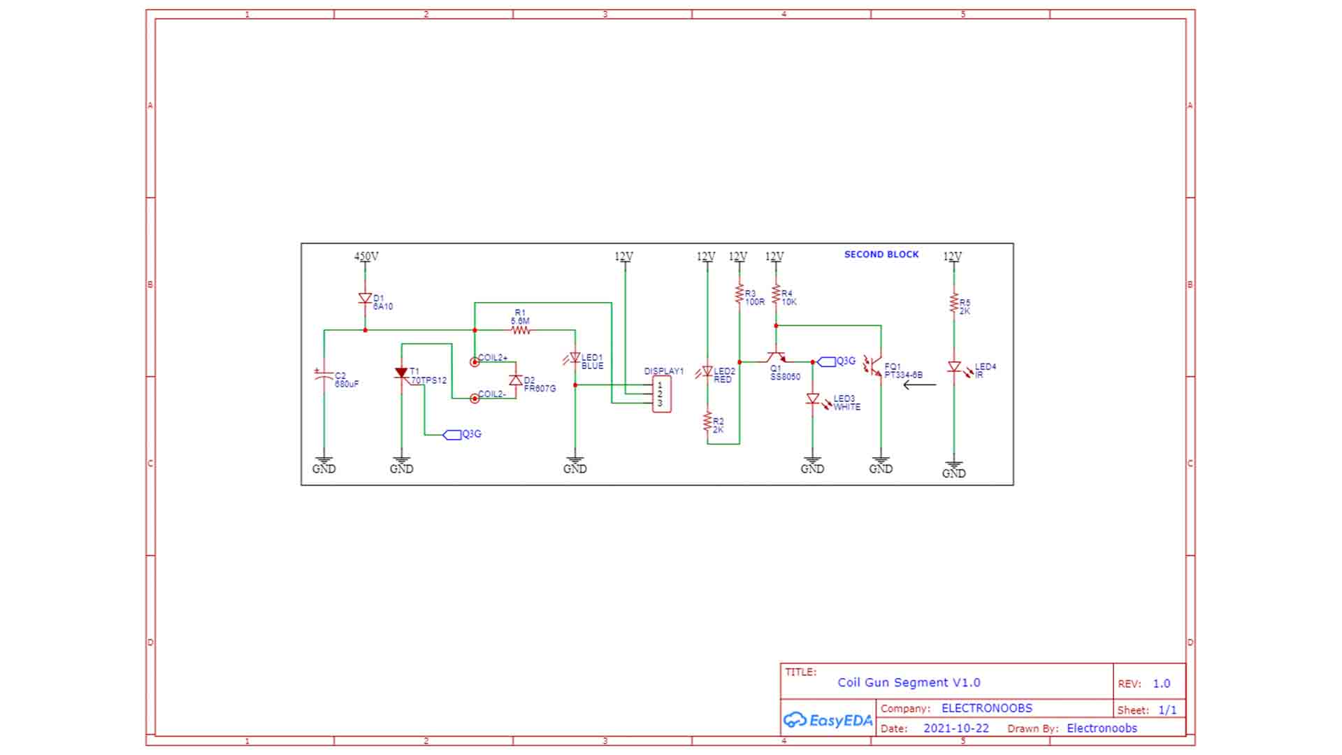
The schematic for the segment is the same but without the first stage controlled by the push button. We can get the signal from the phototransistor detector and apply it to a control circuit that controls a Thyristor. This Thyristor is connected to the coil, so we can turn on and off the power, and with that on and off the magnetic field. When we detect the bullet, we cut off the power so the projectile can continue on the other side. And that’s how is done. The circuit I have for the coil gun segment is something like this below. I have this Thyristor connected to the coil. Its gate is connected to this BJT transistor which is controlled by the infrared sensor output. The circuit is supplied at 450V DC and we will see how to get that voltage in a moment. Since the PCBs have exposed copper pads, we can merge them together and they can share GND and 450V.
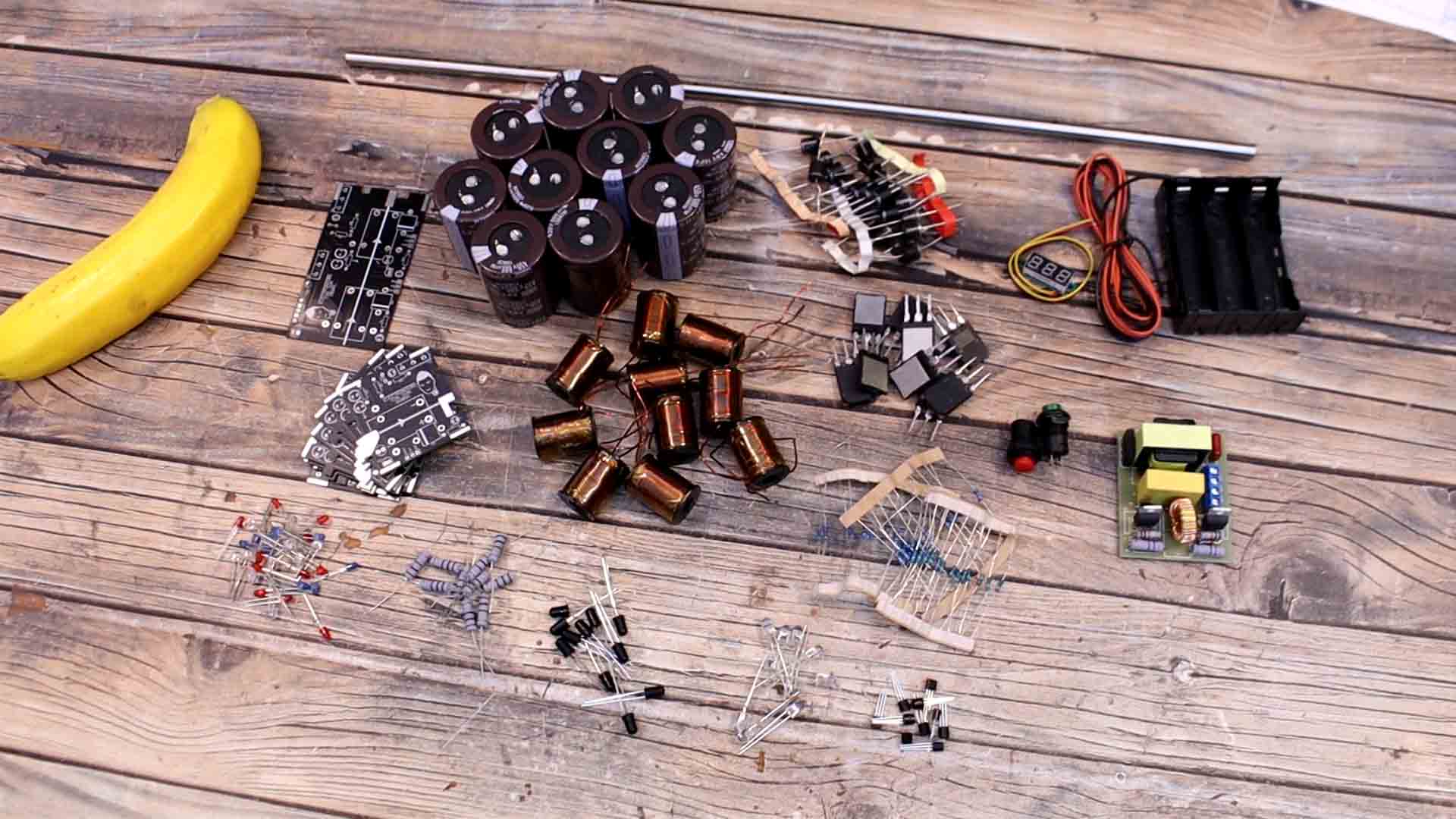
So, we need PCBs, the high voltage capacitors, we also need Thyristors. We need some infrared LEDs and some phototransistors. We also need some BJT transistors. The rest are some resistors and some LEDs. We also need the copper coils. To make these you can download from below my 3D design. Remove the supports and you will be left with a basic support. Then you can add around 150 loops using thick enameled copper wire (0.8-0.9mm) that could withstand enough current. Once you have all the loops, you can add some KEPTON tape on top so the coil will stay that way. Or if you think that’s too much work, you can find these coils to buy on the internet, see below. We also need some powerful diodes and some push buttons to fire the gun. On the other side we need the high voltage module and maybe a 3S battery or even better a battery socket. As projectiles I will use some 6 to 7mm metal rods that you could cut to around 2cm and maybe smooth the edges. As the gun barrel, I will use an 8 mm metal tube. It would be better to use a plastic tube so there would be less magnetic attraction and less friction with the bullet. You have to make holes on this tube from side to side
If you want the same PCB, download my GERBER files from below and remember we need two designs. Then go to PCBWAY.com for example and click the quote now button. You can download them for free, or if you want to help my work, buy the GERBERs from my shop for a few dollars, thank you! The main PCB is 91 by 50mm size and the segment is 50 by 50mm and you can select any color for the soldermask when you order the PCB. In my case I wanted the black color. All components are through hole. The silklayer will show you the component number so is easier to solder following the schematics above.
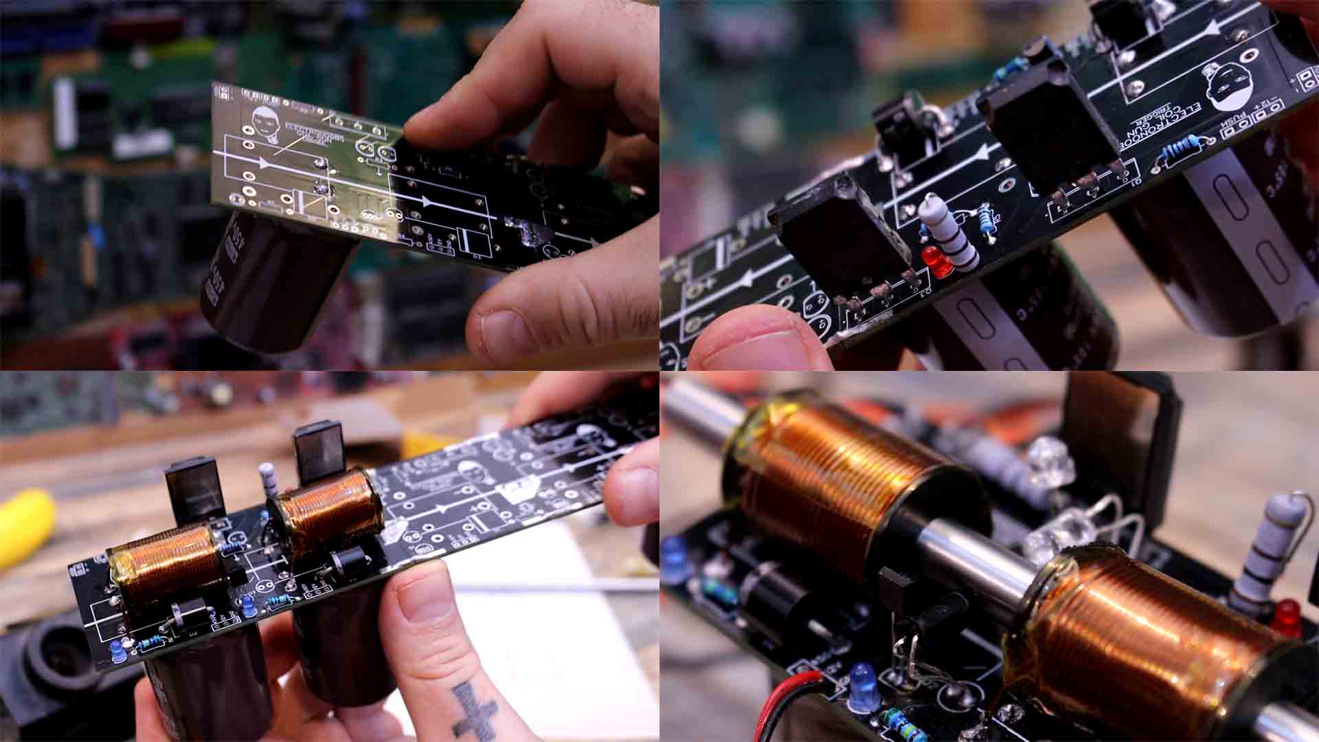
Ok guys so let’s assemble this coil gun. First part is to assemble the main segment. This PCB has two stages and we have the same power control part as before, but the Thyristor is activated with a push button. First, we add the huge capacitor and make sure it is on the bottom part of the PCB since on top we will have the coils. Follow the indications on the PCB in order to know where is positive and negative. Then I solder the diodes. You will see that one diode can’t go through since we have the capacitor below so we have to solder on top of the PCB. Then I add all the resistors for the first and second stage. I add the small BJT transistor for the second stage. Then I add the LEDs but I don’t solder the infrared LED and the phototransistor yet, we do that after we add the coil. Next step is to add the Thyristors and they have the pin connection labeled on the PCB so don’t put them backwards. So now we solder the coil, so measure the wire length and clean out the enamel from the wire. Then you cut it to size and solder the coil on its holes. Now we can measure the LED and phototransistor height and solder them in place so they would be at the height of the coil tube. Also make sure the infrared LED is in face to face with the phototransistor. The first and the second stage are ready.
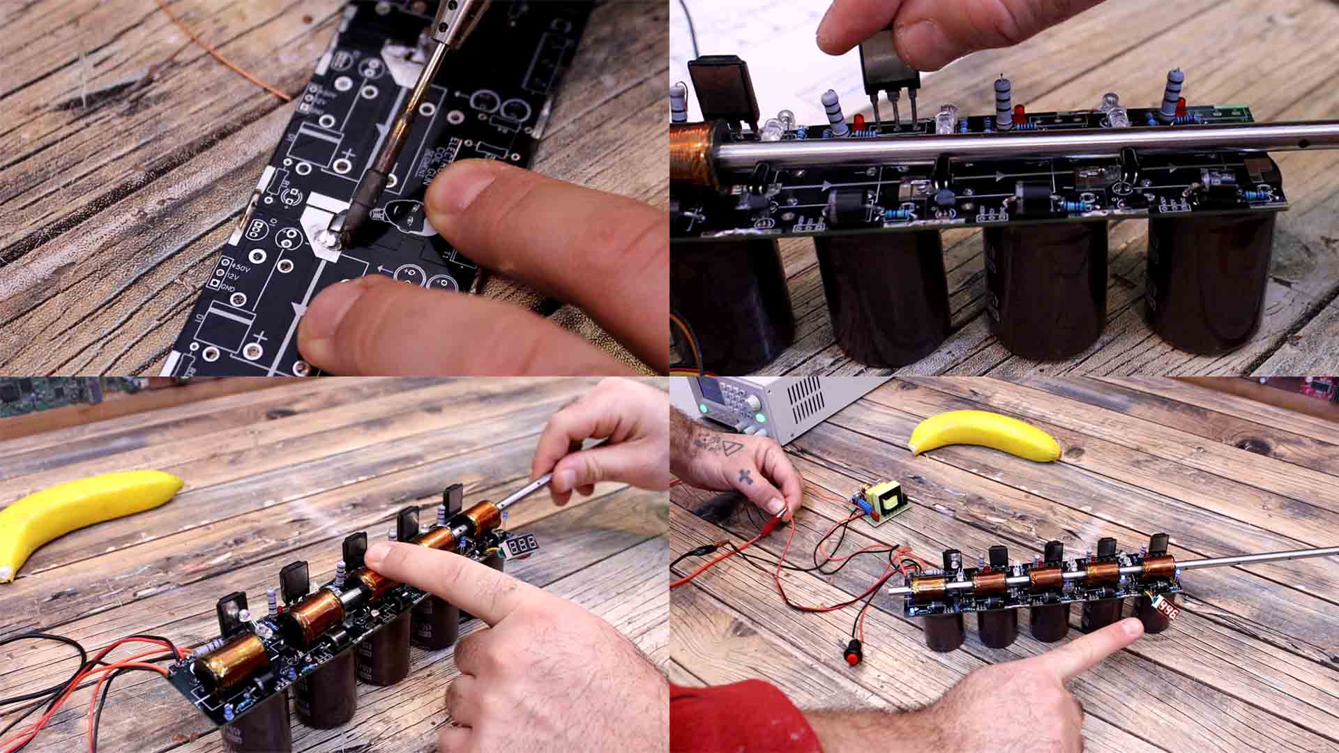
Att his point you could test the first two stages by ading the push button on the "push" pads on the PCB. Aslo by supplying 12V and 450V from the high voltage module. Place the projectile at the input and fire! Is time to add the next stages. The exposed copper connections on the PCB are not just for support. They also carry 450V to the next stages so make sure you don’t touch these pads while the gun is powered on. Use solder and thick wire to merge the stages one next to the other. I solder the components of the next stages as I did with the first ones, the resistors, the Thyristors and the coils. Now I have 5 stages so we can make another test. Add the metal tube and meake sure the holes on the tube are right in front of the IR LEDs and the phototransistors and that each part works properly. Connect 12V and test if the detection part works. The red LED should turn on when the phototransistor is covered so the IR light can't reach it.0 You can add some hot glue on the IR LED and the phototransistor to keep the LEDs in pace if you want.
I add a projectile at the input of the metal tube. I put this cardboard box in front of the gun. I connect power to the high voltage module and as you can see, we charge up the capacitors up to around 500 volts. Now we fire using the push button. Amazing, it passed through both sides of the cardboard box and I’ve got to say, it looks pretty fast and also a bit dangerous. Then I do the same with 4mm balsa wood, 2mm acrylic and 3mm plywood wich is very strong, but even so, it passed without any problem.
Obviously, you can always add more stages and make it of 8, 9, 10 or even more stages but I guess there will be a speed limit given by the speed of the component commutation. Since you now have my design of separated stage, you can always solder one more if you want. But even so, the bullet is very fast. So guys, I hope that you like this project and have in mind this is just the first version. In a future video I will make a case for the electronics, create a support for the gun and give it a better look so stay tuned for that. If my videos help you, consider supporting my work on my PATREON or a donation on my PayPal. Thanks again and see you later guys.