
This is a very basic tutorial. I will show you how to build a constant load controller. What is that? Well, imagine you want to test the efficiency of a power supply. At a certain voltage output, you should create a current values table and get the effiency curve. For taht you need different values of resistance (load). Instead of using resistance, you could use this circuit that by the help of a MOSFET, it can simulate all values of current in a certain range. This circuit can do that preciselly for values from 0 to 5.2A and with a precision of 0.01mA which is quite decent. So, let's see how to make it!
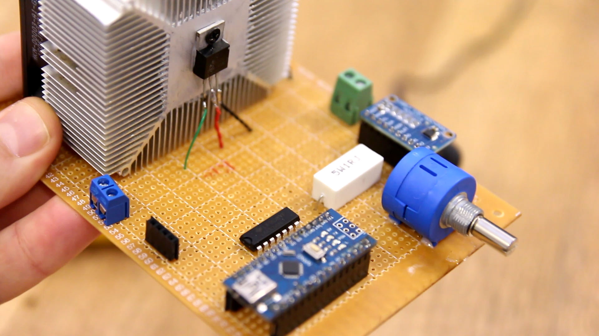
What we need for this project is very simple. A N-channel MOSFET and a power resistor as a load. To control the voltage we need an OPAMP and a potentiometer. The rest are just other components in order to read and show the values on the display. The potentiometer must be at least 10 turns in order to have good precision. Very important, you need a good heat dissipator because the MOSFET will get hot fast and without it it will burn out in seconds. See the full list HERE
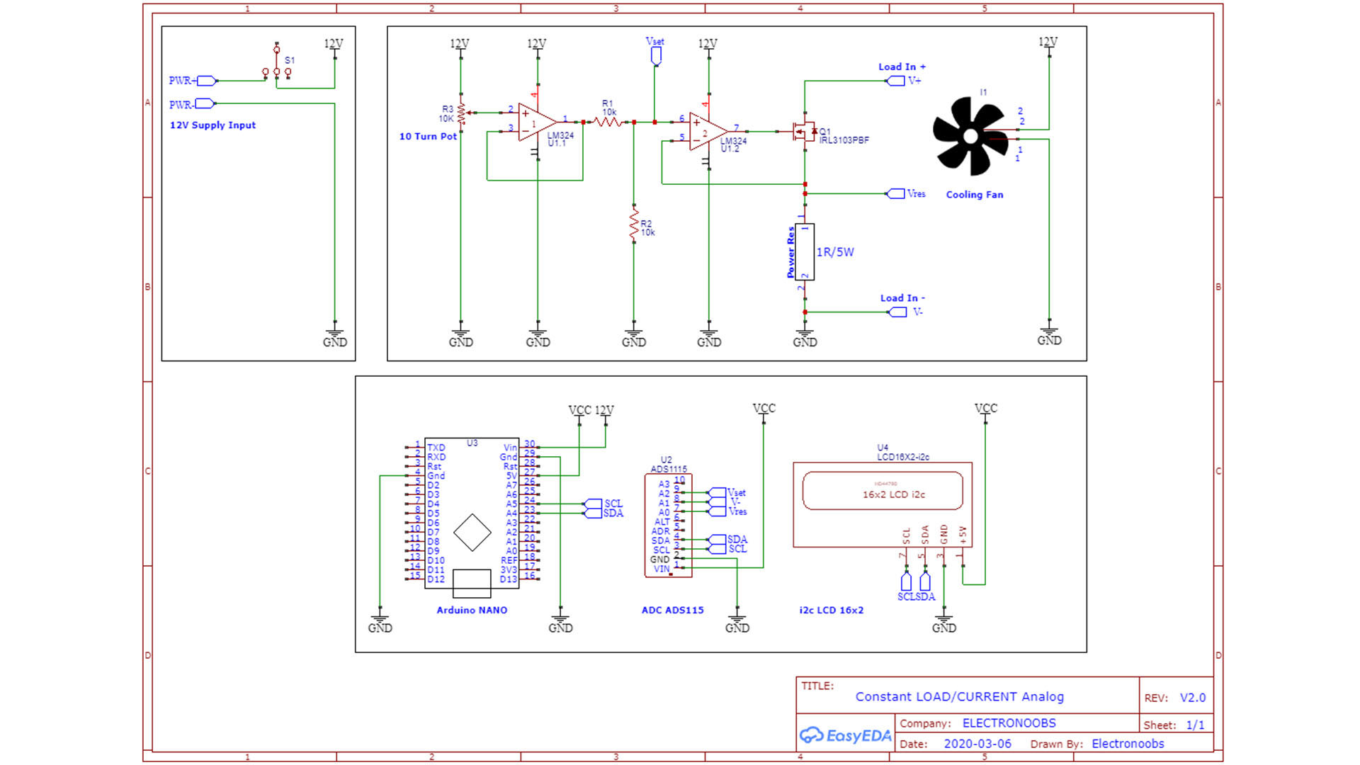
The Schematic is very simple. We supply everything with 12V from the DC transformer. Connect 12V to the OPAMP positive, to the DC fan and to the Arduino Vin pin. From the Arduino 5V pin we get our Vcc and connect that to the digital parts such as the LCD and the ADS1115. Connect the i2c pins from the display and ADC to the Arduino. Connect the 10 turns potentiometer with one pin to 12V, the other to ground and the middle one to the first positive input of the OPAMP. We use a second OPAMP just to have a follower and divide the voltage a little bit with that voltage divider, but we could make this with a single OPAMP as well. Connect the second OPAMP output to the gate of the MSOFET. At the source of the MOSFET, conenct the power resistor of 1 ohm. The source of the MOSFET will also be connected to the ADC input A0 in order to read the real current value. The positive input of the second OPAMP is connected to the ADC input A2 in order to read the setpoint value. Also conenct the V- refference to the ADC input A1 in order to read the voltage drop on the power resistor.
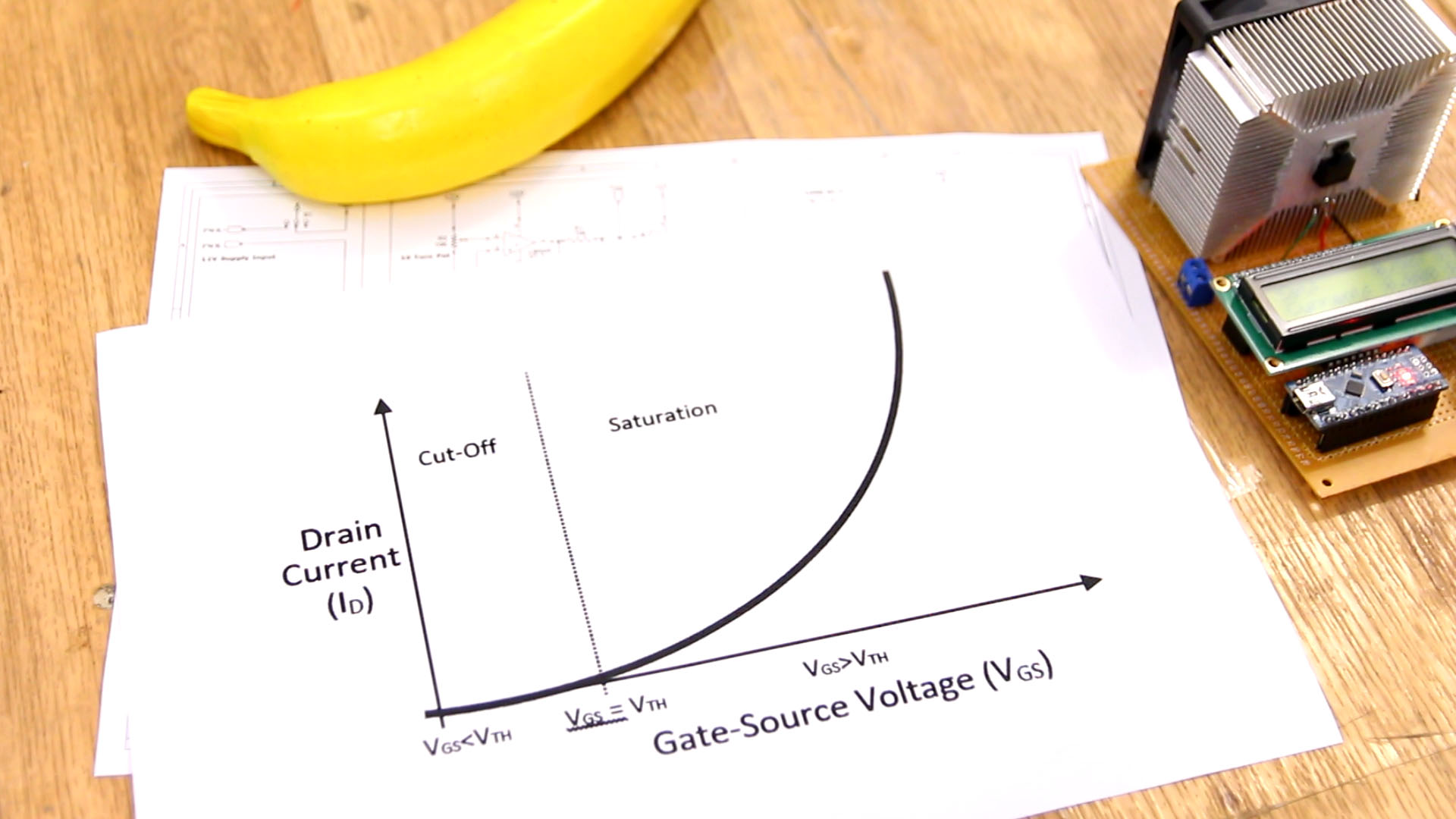
So, how dose this circuit works? Well, the MOSFET is controlled by voltage on its gate. Till the voltage between gate and source (Vgs) is not higher than a certain value called Vth, the MOSFET is disabled so no current if flowing between drain adn source. After Vth, the MOSFET starts a current flow and the value of this current will get higher when the Vgs is getting bigger as well till a certain value where the MSOFET is fully on. So, taht easy, by varying the voltage at the gete we change the current flow and by that we simulate the load value. But there is no relation between the voltage at the gate and the current value. For that we add a 1 ohms resistor at the source of the MOSFET. Since we know for sure the resistor is 1 ohm, for example, when 1 amp is flowing, we will have 1V voltage drop on this resistor and we can measure taht with a precise ADC. In this way we know the current value.
The OPAMP is very important! Since we can't know what voltage to put at the MSOFET gate in order to get any current value, we use the OPAMP and this will do that for us automatically. Let's say we want a current flow of 1A. All we need is to get 1V voltage drop on the power resistor. That point, as you can see in the schematic, is connected to the negative input of the OPAMP. We know the theory of operational amplifiers and by that we know the OPAMP will do all is necessary to have the same voltage on the input V- as on input V+. So if we palce 1V at V+, the OPAMP will change the voltage at the MOSFET gate till the voltage on the resistor is 1V as well, since that point is connected at input V- of the OPAMP. So, just like that, we can get any value of current that we want...
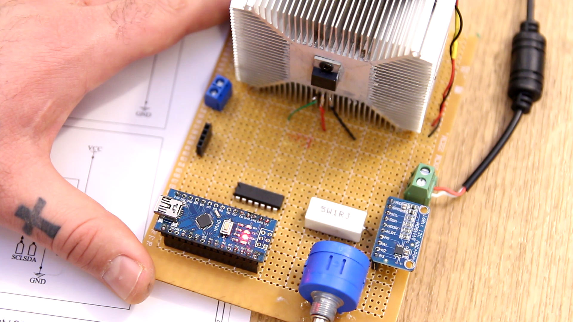
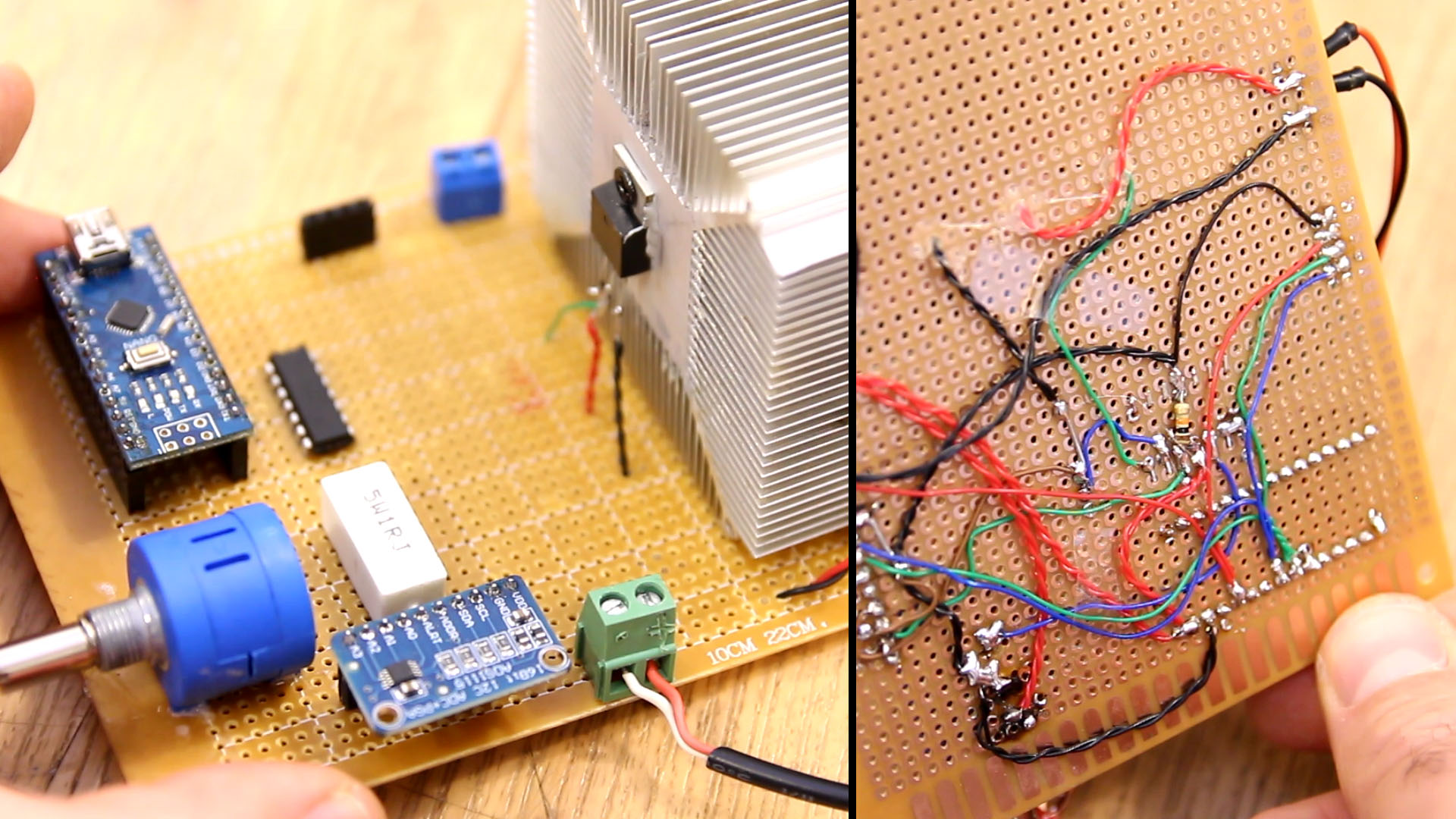
Get the PCB and the components and make all connections as in the scheamtic. For the Arduino, LCD and ADC, I add some female pins so we could remove those whenever we want. The MOSFET is soldered with wires and placed on the cooler using some thermo paste in order to better transfer heat. Make sure you use thick wires. In my case I've used some wires taht are not thick enough so don't make the same mistake. Add PCB terminals for input and output. Make sure the fan will be turned on when using the controller. Now, downlaod the code from next part and upload it to the Arduino and test it.
Get the code from below. You will also need the i2c liquid crystal library and the ADS1015 library for the ADC. Download those from below as well and install them to the Arduino IDE. To do taht go to Sketch, include library and add .ZIP library. There selct the downloaded zip file from belwo and the library will be installed. Copy the code from the link below or download the zip fle with the code. Compile and uplaod the code to the Arduino and test the constant load controller.
  float set_val, real_val;
  real_val = ads.readADC_Differential_0_1();      //Read DIFFERENTIAL voltage between ADC0 and ADC1
  set_val  = ads.readADC_SingleEnded(2);          //Read voltage on potentiometer (this will be our setpoint)
  set_val = (set_val * multiplier) - offset;      //Pass to real voltage and substract offset
  real_val = real_val * multiplier - offset;
That's it. Uplaod the code power up the PCB with 12V from the DC transformer. When the controller is on, connect a power supply at the load input terminals. I set the supply at 15V for example. Then by using the potentiometer, I increase the load and get current values from 0 to 5.2A as you can see below. Resolution is 0.01mA and that's quite nice! The MOSFET was always very very cool so I'm sure we could go to more current by lowering the power resitor to maybe 0.5 ohms.
I hope this will help you. Consider supporting me on PATREON or you can help me on PayPal. Thank you very much!


