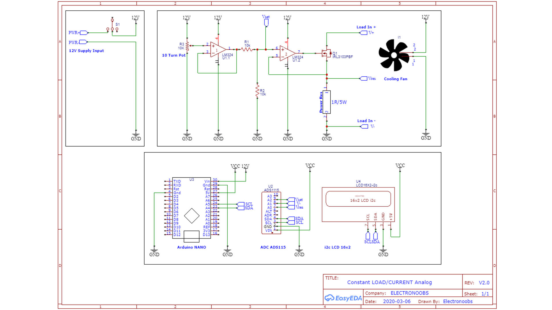
The Schematic is very simple. We supply everything with 12V from the DC transformer. Connect 12V to the OPAMP positive, to the DC fan and to the Arduino Vin pin. From the Arduino 5V pin we get our Vcc and connect that to the digital parts such as the LCD and the ADS1115. Connect the i2c pins from the display and ADC to the Arduino. Connect the 10 turns potentiometer with one pin to 12V, the other to ground and the middle one to the first positive input of the OPAMP. We use a second OPAMP just to have a follower and divide the voltage a little bit with that voltage divider, but we could make this with a single OPAMP as well. Connect the second OPAMP output to the gate of the MSOFET. At the source of the MOSFET, conenct the power resistor of 1 ohm. The source of the MOSFET will also be connected to the ADC input A0 in order to read the real current value. The positive input of the second OPAMP is connected to the ADC input A2 in order to read the setpoint value. Also conenct the V- refference to the ADC input A1 in order to read the voltage drop on the power resistor.