Usually, each time I have a project with a small battery that I also want to charge, I use a small charging module with USB connector. But then, all the other digital components usually work at 5V, but the battery is 3.7V. So, for that I add another small module, a boost converter to give me 5V. Usually we also need a battery protection so it won't overcharge, discharge or have a short circuit. What I've done was to add all these ICs on the same PCB so now we can charge a 3.7V LiPo or Li-Ion battery, protect it and then have a 5V or 12V boosted output. Let's see how I've made it.
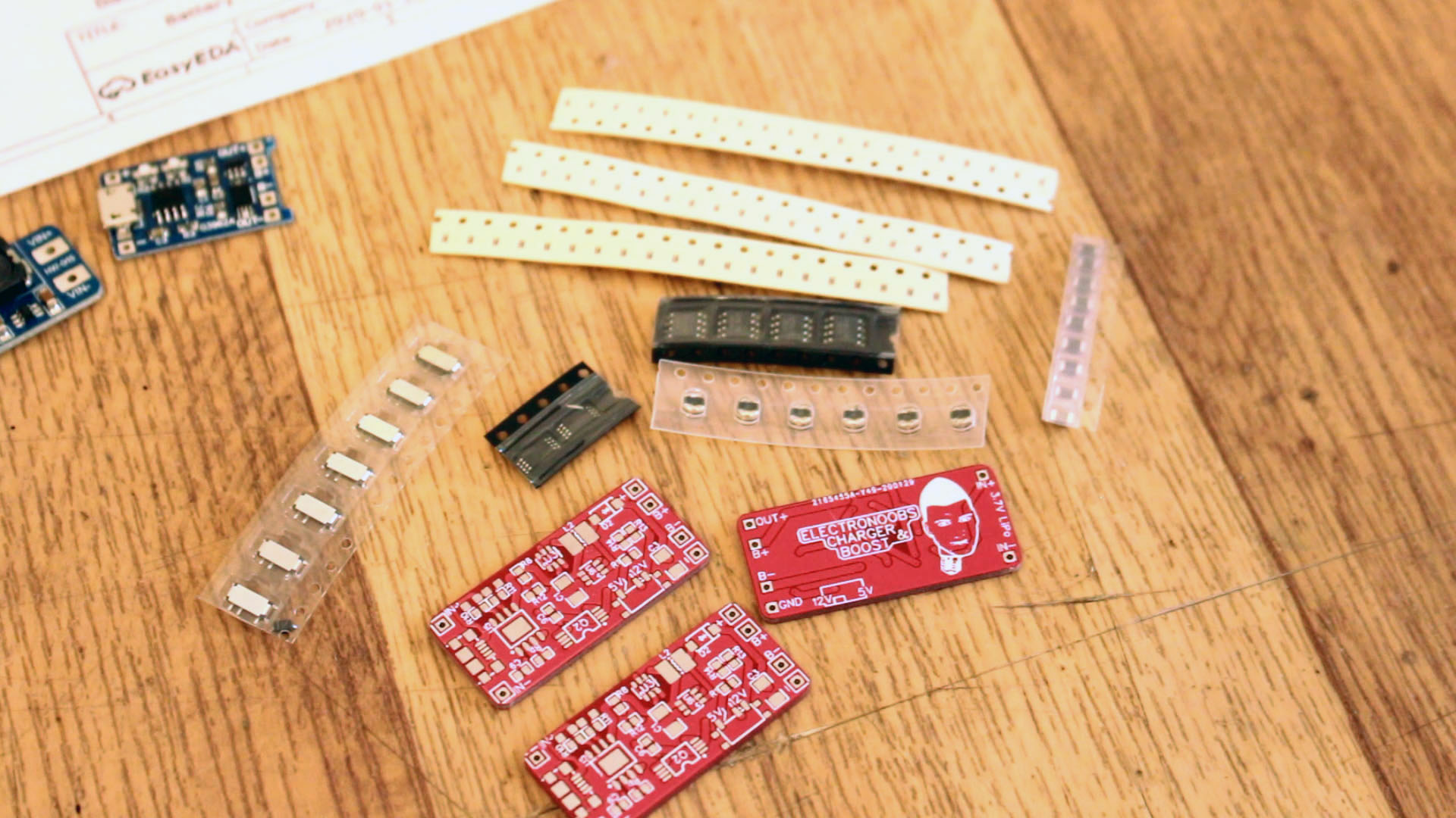
First of all we need the PCB I've designed. Go below and get the first version or on my shop and get the second version (thanks for the support). Once you have the GERBERs for the PCB, send them to JLCPCB and thet the baord. Then you will need 4 basic ICs for charging, protection, enable output and the boost converter IC. The rest are just smd resistors, capacitors, LEDs and a toggle switch. Oh, and you will also need a micro B USB connector. See the fill list HERE
Below you have the scheamtic for version V1.0. Remember this version works ok
You have the values of each resistor, capacitor, inductor on the schematic. Use the same values in order to get the same output. Remember that Rprog will set the charging current for the battery.
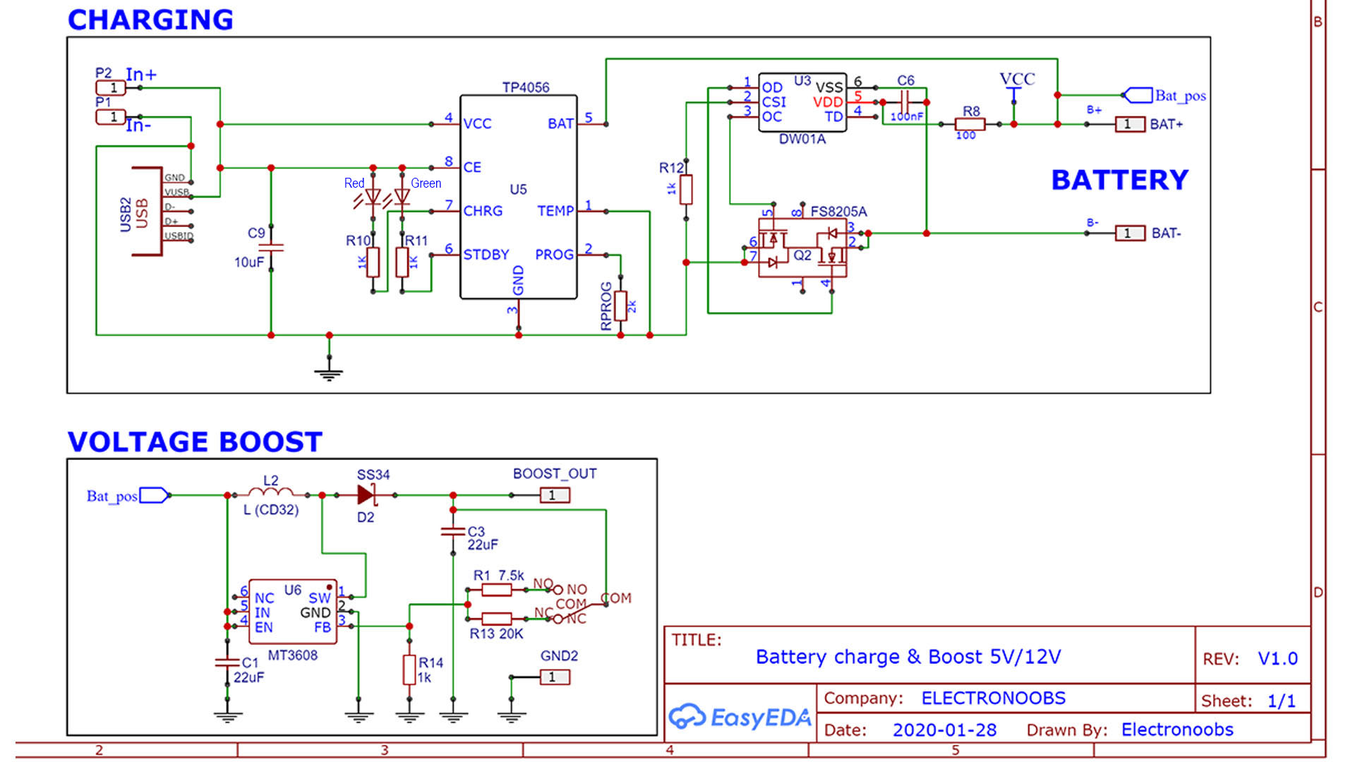
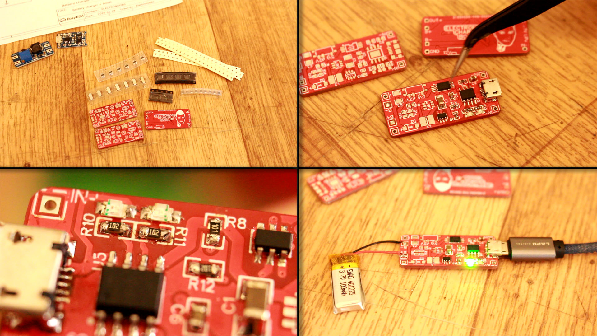
The first step of mounting this PCB is to solder all the battery charging ICs. Those are the TP4056, the DW01A and the FS8205A. Also solder the C9 capacitor, R10 and R11 resistors together with the red and green LED. Solder the Rprog resistor of 2K to limiut the charging current at 580mA. See ther TP4056 datasheet here, in order to know more about this. Finally, solder the R12 and R8 resistors and also the C6 capacitor. Remember to add the USB connector and the C9 of 10uF capacitor at the input and the charging part should now work
To test it, connect a 3.7V battery at the B+ and B- pads. Then connect a 5V usb connector from a PC or a charger. The red LED shoud turn on and the battery will be charging up. When the battery is full, the green LED should turn on and the charging process will be stopped. At this time you cluld also test the over voltage, over discharge and short circuit protection. If this works, we can keep soldering the boost converter part.
Ok, now that the charging process works, first remove the battery and USB cable and then we can solder the rest of the components. Solder the MT3608 boost converter IC and the needed components such as the coil, diode and the voltage set resistors. Remember to add the sliding switch and the output capacitor C3 of 22uF. Now you shoud test if it works.
● You can't change voltage from 5V to 12V while battery is connected
● So, first remove battery and then select deired voltage.
● When the voltage is set to 5V or 12V, you can connect back the battery
Once you do these 3 steps, you can test the outpur. I've used my power supply as input voltage, so we could change the input voltage and make the tests. In the next part we make the tests and that's it.
Is time to make some tests of our PCB. You must make 4 main tests:
● If the 5V and 12V output works
● Lower the voltage below 2.6V and test over-discharge protection
● Connect a battery and the USB cable. Test if charging process stops at 4.2V
● While working, short circuit the output and see if the output is disbled
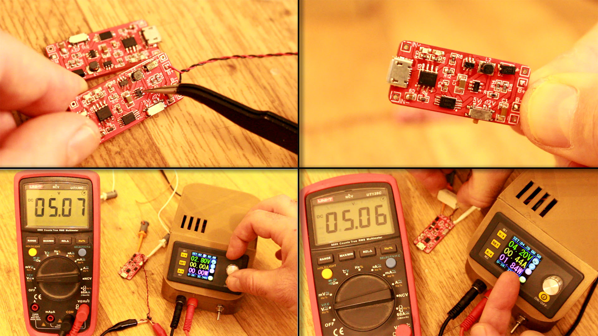
Ok, so to make the 5V and 12V output test you must do this. First make sure the battery and USB cable are not connected so the PCB is totally off. Then set the votlage to 5V with the switch. Connect the battery and measure the output with a multimeter. It should be around 5.1V. Now, very important, remove the battery and then swith to 12V. Connect back the battery and measure the output. It should be around 12.5V.
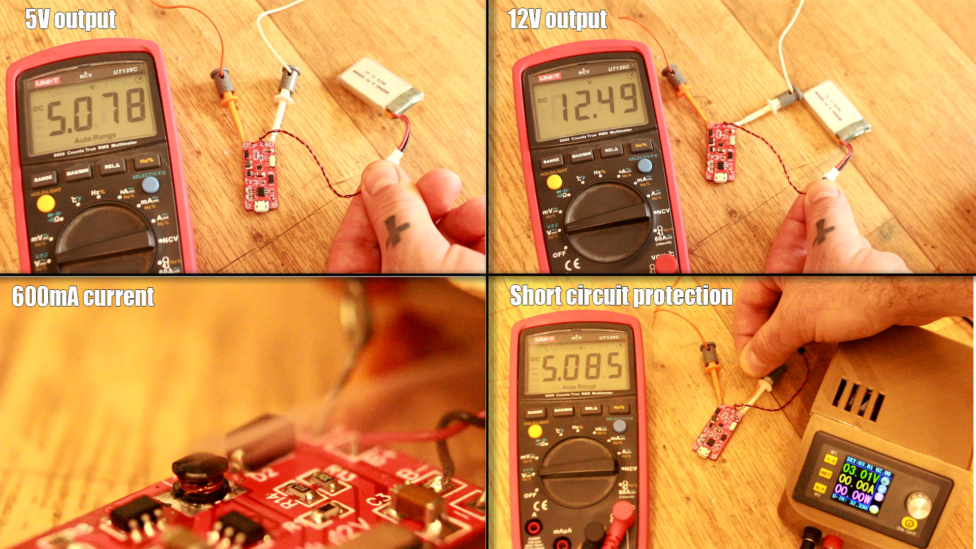
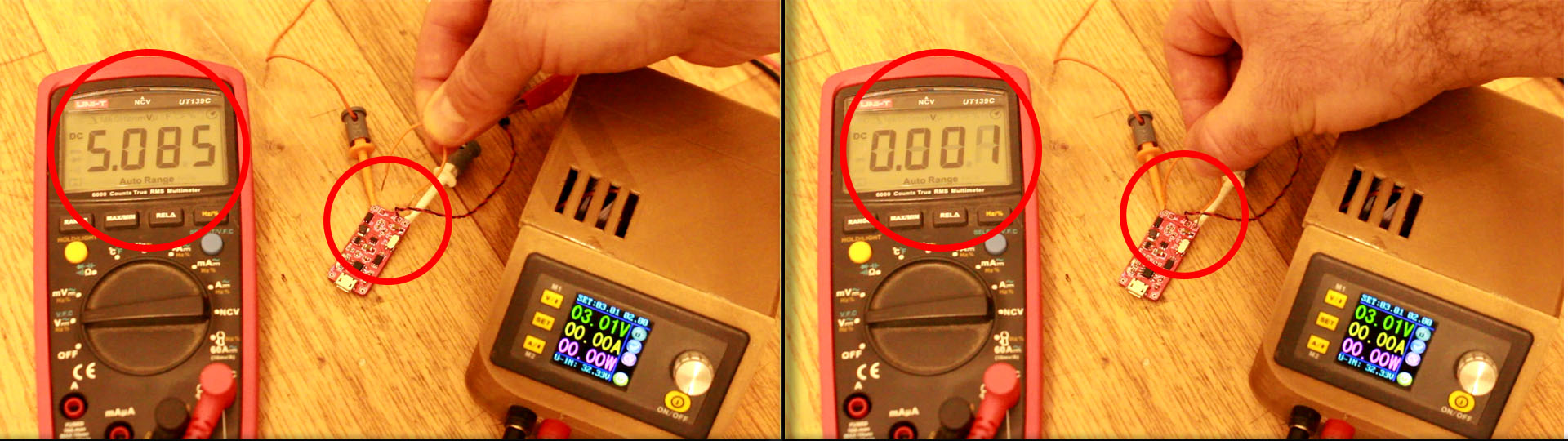
To test the short circuit protection just connect at the B+ and B- pads the battery (or a power suplly set to a voltage between at 3.7V and 4.2V). Check the output if is 5V or 12V and let the multimeter connected at the output so we can see if the votlage will drop. Then take a short wire and short circuit the output. The output should go to 0V and stay there even if you remove the wire. The output will be enabeled once again only if you connect the USB cable so the TO4056 will give a signal or if you remove the battery and connect it back. Test that as well. If that works, the short circuit protection is ok.
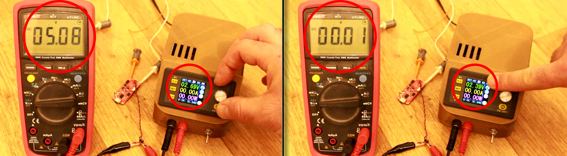
For this test you need your multimeter and a variable power suplly. Connect the supply at the B+ and B- pads with a voltage of maximum 4.2V. Measure the output with the multimeter and see if is 5V or 12V. Then start lowering the input voltage with tge variable supply. You should see taht below 2.6V the output is disabeled and it will go to 0V. The output will be enabeled once again only if you connect the USB cable so the TO4056 will give a signal or if you remove the battery and connect it back. Test that as well. If that works, the over discharge protection is ok.
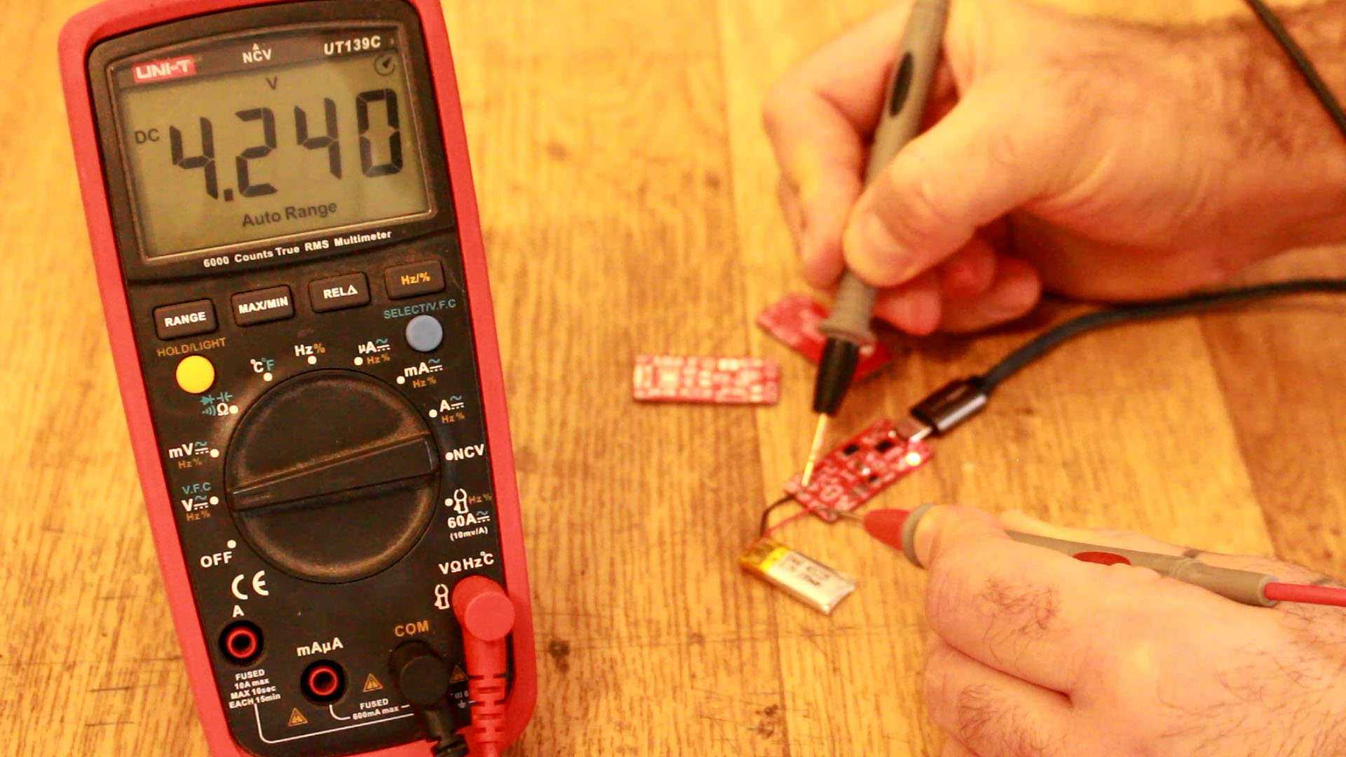
For this test connect the 3.7V battery at the B+ and B- pads. Connect the multimeter at the same pads. Then connect the USB cable so the charging process will start and the red LED will be on. After a while the red LED will turn off and the green LED will turn on. At this moment you must check that the battery voltage is 4.2V. Also remove the USB cable adn test again if the battery is 4.2V. That means the over charge protection works and the IC will always stop the charging process when 4.2V are reached.
Below you have the full tutorial with all the tests. Remember to check my shop if you want the versions V2.1 or V3.0 for just a few dollars and by taht support my work. V1.0 will be always free. Consider supporting my videos on PATREON. Thank you!