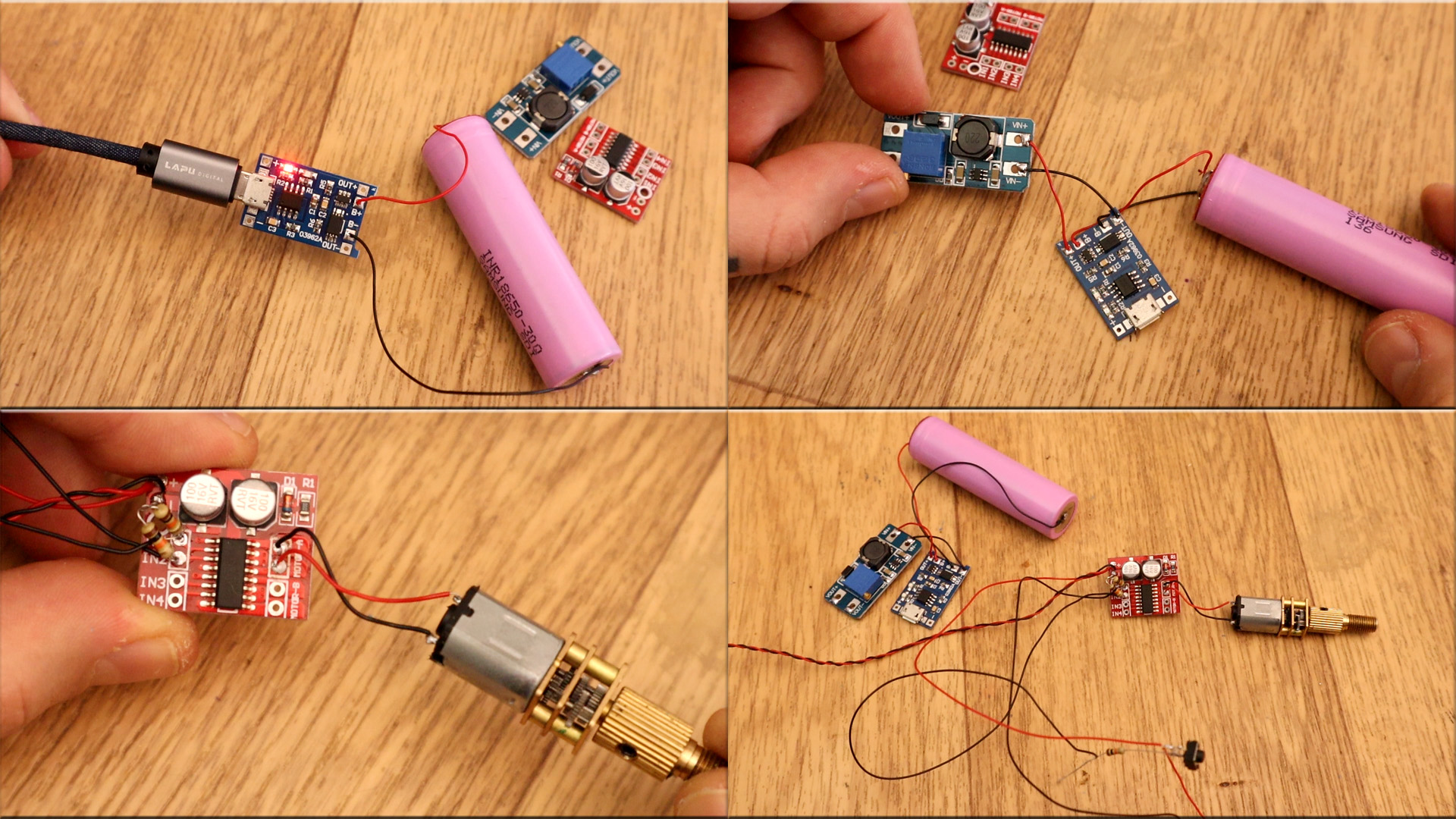

Another basic tutorial. The circuit and design is very simple. We havea li-ion battery taht will supply everything. We also have a charging module for that battery. The project uses a DC motor with a high torque gear box so it is very powerful. To control rotation, an H-bridge is used so the direction can be controlled.
First, let's see the schematic. As you can see we start with the TP4056 module connected to the battery. From the battery, which has only 3.7 to 4.2V, we need higher voltage to have higher speed of the DC motor. We set the boost converter to an output of 12V. That is connected to the H bridge based on the MX1508 chip. The 12V is also connected to the push buttons. At the output we connect the DC motor.

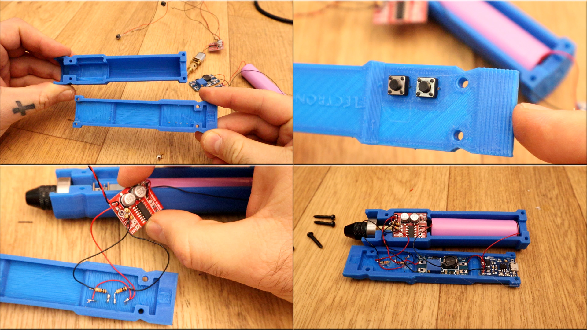
Ok, the case is amde out of 2 parts and it is printed using PLA material, 0.4mm nozzle, 0.3mm layer height and 20% infill. The case has space for the battery and all the components. Make sure you use the same components as I did, otherwise they won't fit in this 3D case.
First we make the main connections. Battery to charging modules, the H-bridge adn the motor. Then is time to mount everything inside the case. Also, add the push buttons to the top part of the case.

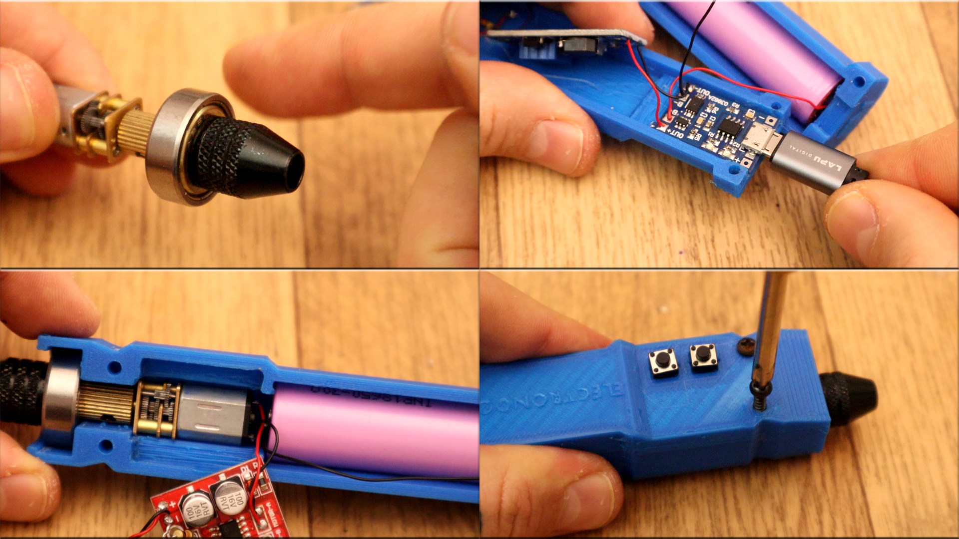
We add the bearing to the motor shaft, we add the drill bit support and fit the motor inside. We also fit the battery, shorten the cables and guel the modules in place with some hot glue. Make sure the push buttona are working.

Some close up looks to how everything is inside. Make sure you have good connections and in the schematic. Also test if the charging module works with any USB connector and 5V. Close the case using some 3mm small screws. And that's it.
