
This is another basic circuit tutorial. We know PIR modules will give a high output any time they detect changes in the infrared radiation and by that, detect movement. So, we could connect that high output to a relay and by that turn on or off high voltage, 220V AC in this case. But, the output from the PIR module will be high just for 2 or 3 seconds. So, for that we have to add a delay circuit and that's exaclty what we have in this tutorial.
First, let's see the schematic. We know that we will work with high voltage, 220V AC so be careful. To get 12V DC for our circuit I've used these small transformer modules that could give me 12V DC from 220V AC. So, now we haev our circuit supplied and the Vcc is 12V in this case. make sure your PIR module could work at 12V as well, if not, use 5V regulator. The relay is connected to normally open (NO) so we need to invert the PIR signal so for that, first, the PIR module will activate the gate of Q1 NPN transistor. That will turn off the Q2 transistor and whrn Q1 is off, well Q2 is on and by taht the signal is inverted.

Now, when Q2 transistor is activated the C1 capacitor is not charging. But when the capacitor C1 get's charged, it will activate Q3 transistor and taht will activate the relay to swithc to NC or normally closed and by that turn on the light bulb. If the PIR module stays deactivated, the C1 capacitor will slowly discharge till it gets below the activation voltage. Then, Q3 turns off and the light bulb as well.

So, the PIR short pulses activates Q1 that will deactivate Q2 so C1 can get charged through the R3 resistor. After the PIR short pulse ends, C1 will slowly dicharge and the time is given by the resistance of R5 potentiometer. The bigger is the resistance value, the slower will C1 discharge so the light will stay on for more time.
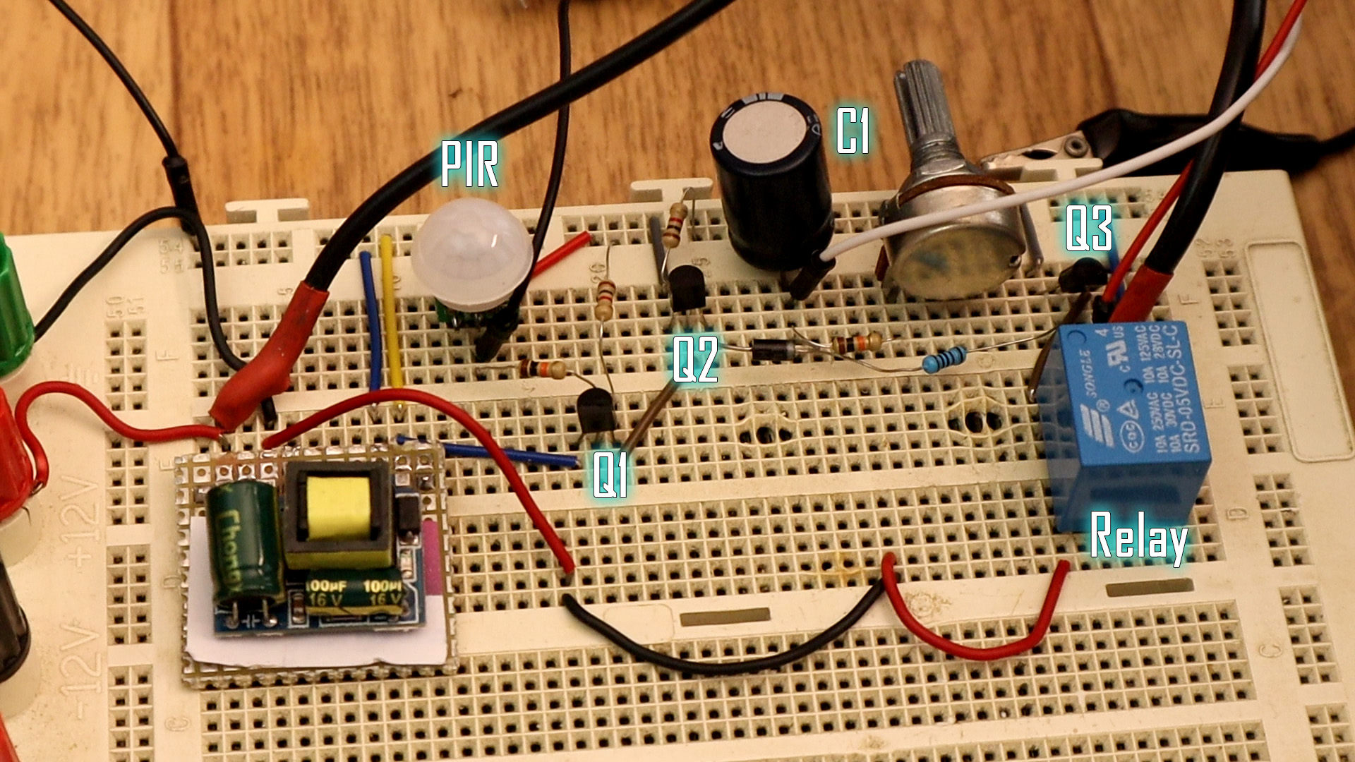
I've mounted the schematic to the breadboard for tests. I was able to change the delay time from 5 seconds up to 60 seconds using a 500K potentiometer. Using higher resistance potentiometer will increase the delay. Also changing R4 resistor will increase the minimum delay as well.
As you can see in the video below, after I activate the PIR module the C1 (blue line) gets charged very fast but discharges slowly. When C1 is discharged the relay turns OFF and the light bulb as well. That's how this PIR switch works. Quite easy right?


