About me
  History
  Let's learn
  Contact us
  Arduino tutorials
 Circuits tutorials
  Robotics tutorials
 Q&A
Q&A Blog
Blog  Arduino
  Circuits
 Robotics
  Modules
  Gadgets
  Printers
  Materials
  3D objects
  3D edit
  Donate
  Reviews
  Advertising


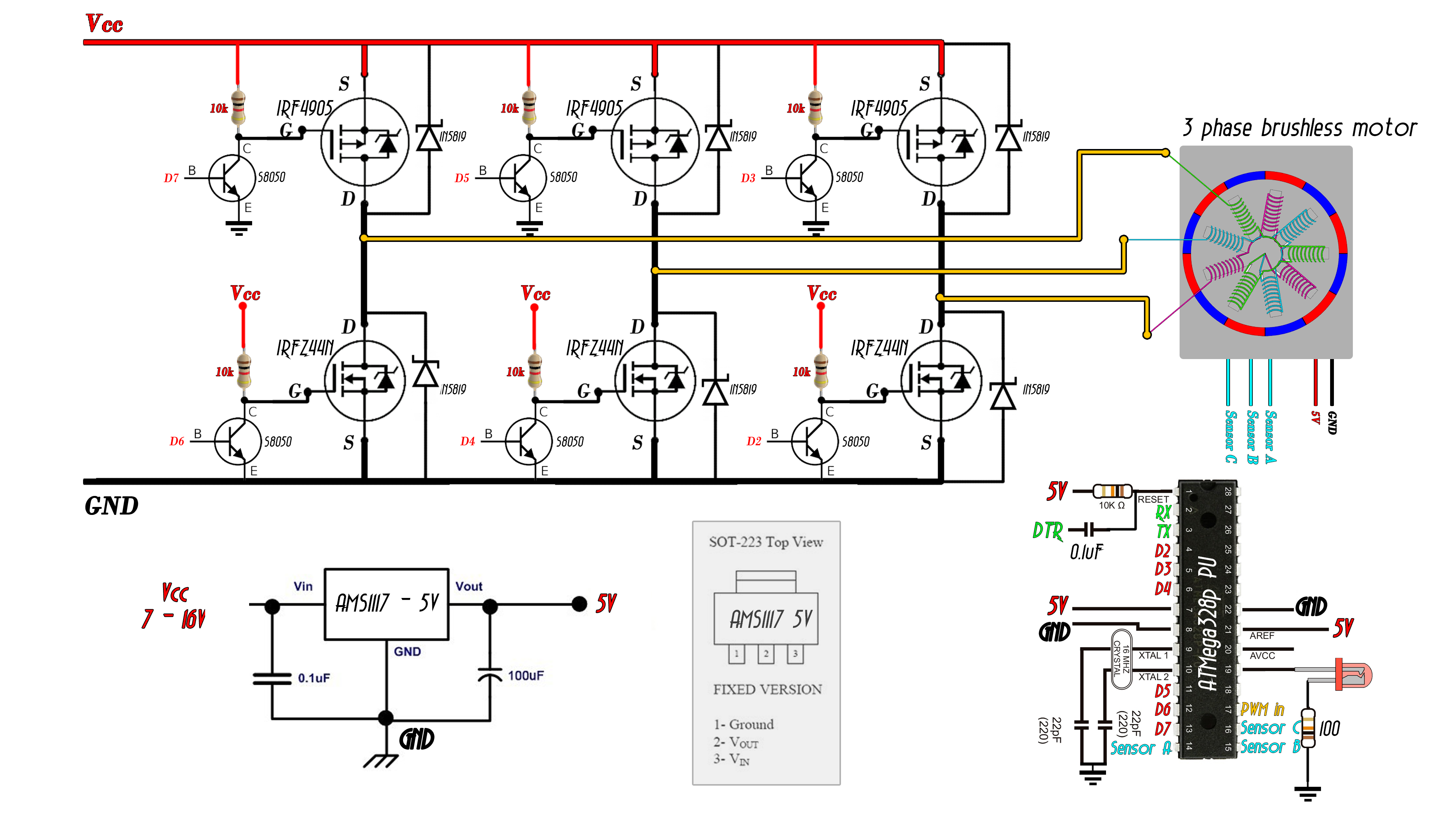
Homemade sensored ESC (PWM input code)
Download the .zip file below. Install it on your Arduino IDE.
This code is for the schematic with the PWM input for the speed control. Read all the comments in the code.
/*
 * Electronoobs sensored brushed motor electronic speed controller code
 * Connect the sensors to pins 8, 9 and 10
 * High gates to pins 7, 5 and 3
 * Low gates to 6, 4 and 2
 * More on http://www.electronoobs.com/eng_circuitos_tut19.php
 */

int pot = A3;
int SensorA = 8;
int SensorB = 9;
int SensorC = 10;
int pwm_pin = 11;

//We create variables for the time width value of the PWM input signal
unsigned long counter, current_count;
byte lastPWM_state;
int PWM_width = 1000;

int fase = 1;
int Delay=4000;
unsigned long previousMillis = 0;
unsigned long currentMillis = 0;

int fase = 1;
int Delay=4000;
unsigned long previousMillis = 0;
unsigned long currentMillis = 0;

void setup() {
  //Define sensor pins and potentiometer as inputs
  pinMode(pot,INPUT);
  pinMode(SensorA,INPUT);
  pinMode(SensorB,INPUT);
  pinMode(SensorC,INPUT);
  pinMode(pwm_pin,INPUT);


  DDRD  |= B11111100;  // Sets D2, D3, D4, D5, D6 and D7 as OUTPUT
  PORTD &= B00000011;  // D2-D7 LOW
  PCICR |= (1 << PCIE0);    //enable PCMSK0 scan
  PCMSK0 |= (1 << PCINT0);  //Set pin D8 trigger an interrupt on state change.   sensor A
  PCMSK0 |= (1 << PCINT1);  //Set pin D9 trigger an interrupt on state change.   sensor B
  PCMSK0 |= (1 << PCINT2);  //Set pin D10 trigger an interrupt on state change.  sensor C
  PCMSK0 |= (1 << PCINT3);  //Set pin D11 trigger an interrupt on state change.  PWM input for speed

  currentMillis = micros();
}


void loop() {

  currentMillis = micros();
  if(currentMillis - previousMillis >= Delay){

    previousMillis += Delay;

    if(PWM_width > 1070)
    {
      switch(fase){

        //Phase1 A-B
        case 1:
        PORTD = B10010000;  //  Pin 7 and 4 to HIGH
        break;

        //Phase2 C-B
        case 2:
        PORTD = B00011000;  //  Pin 3 and 4 to HIGH
        break;

        //Phase3 C-A
        case 3:
        PORTD = B01001000;  //  Pin 3 and 6 to HIGH
        break;

        //Phase4 B-A
        case 4:
        PORTD = B01100000;  //  Pin 5 and 6 to HIGH
        break;

        //Phase5 B-C
        case 5:
        PORTD = B00100100;  //  Pin 5 and 2 to HIGH
        break;

        //Phase6 A-C
        case 6:
        PORTD = B10000100;  //  Pin 7 and 2 to HIGH
        break;
      }//end of switch
    }//End of if 1070
  }//Case of if millis

  else
    {
      PORTD = B01010100;  //  Else we stop everything
    }

    Delay=map(PWM_width,1000,1800,3000,10);

}//Void end


ISR(PCINT0_vect){

  current_count = micros();

  if(PINB & B00001000 ){
    if(lastPWM_state == 0){
      lastPWM_state = 1;
      counter = current_count;
    }
  }
  else if(lastPWM_state == 1){
    lastPWM_state = 0;
    PWM_width = current_count - counter;
    }


  //This part will run any time any of the sensor pins will change its value.
  if(  (PINB & B00000101) && fase == 6  ){
    fase = 1;
  }

  if(  (PINB & B00000100) && fase == 1 ){
    fase = 2;
  }

  if(  (PINB & B00000110) && fase == 2 ){
    fase = 3;
  }

  if(  (PINB & B00000010) && fase == 3 ){
    fase = 4;
  }

  if(  (PINB & B00000011) && fase == 4 ){
    fase = 5;
  }

  if(  (PINB & B00000001) && fase == 5 ){
    fase = 6;
  }
}