
 About me
  History
  Let's learn
  Contact us
  Arduino tutorials
 Circuits tutorials
  Robotics tutorials
 Q&A
Q&A Blog
Blog  Arduino
  Circuits
 Robotics
  Modules
  Gadgets
  Printers
  Materials
  3D objects
  3D edit
  Donate
  Reviews
  Advertising


Sensored ESC - Homemade
Part 5 PWM input code
In the code, I set pin 11 as the PWM input. In the interruption vector I detect each time that pin change its state and measure the time between each pulse. I map that value to a delay from 3000 to 10 microseconds. The rest of the code is the same but now we won't use the potentiometer to change the speed but the input PWM signal with a width between 1000 and 2000 us.
ISR(PCINT0_vect){
  current_count = micros();
  if(PINB & B00001000 ){
    if(lastPWM_state == 0){
      lastPWM_state = 1;
      counter = current_count;
    }
  }
  else if(lastPWM_state == 1){
    lastPWM_state = 0;
    PWM_width = current_count - counter;
    }

  //This part will run any time any of the sensor pins will change its value.
  if(  (PINB & B00000101) && fase == 6  ){
    fase = 1;
  }

  if(  (PINB & B00000100) && fase == 1 ){
    fase = 2;
  }

  if(  (PINB & B00000110) && fase == 2 ){
    fase = 3;
  }

  if(  (PINB & B00000010) && fase == 3 ){
    fase = 4;
  }

  if(  (PINB & B00000011) && fase == 4 ){
    fase = 5;
  }

  if(  (PINB & B00000001) && fase == 5 ){
    fase = 6;
  }
}
Final code (PWM input)
Now I make the test once again but now using my radio transmitter and the PWM receiver. I can start/stop the motor and also control the speed using the radio transmitter just as any other commercial ESC.
Part 6 Final schematic
Now I use this final schematic and mount the entire circuit on this drilled PCB and using the ATMEGA 328 chip with the 16MHz crystal oscillator and all the components that we need to make it work. I also have a 5V voltage regulator for the ATMEGA chip and that will also supply the OPAMP for the motor sensors.
See the full scheamtic here:
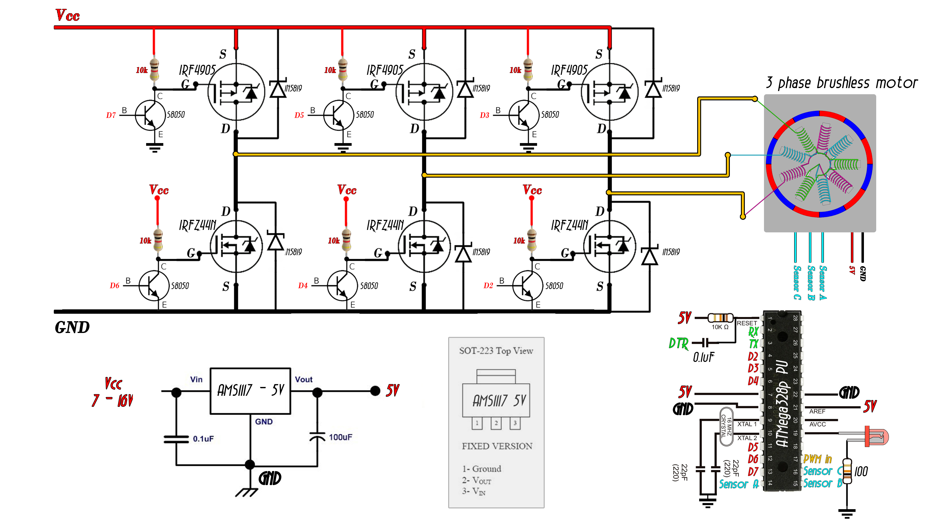
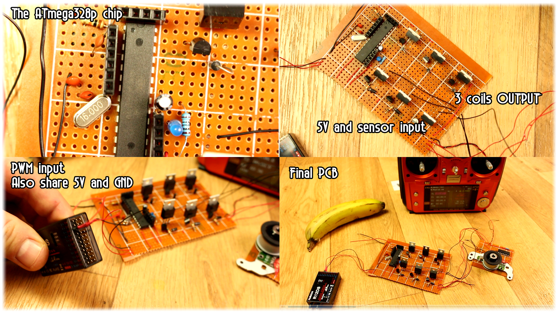
I use an external FTDI module, I connect the RX, Tx and DTR pins and upload the code. The PCB has and input for the PWM signal from the radio receiver and shares both 5V and ground.
Part 7 Final PCB
In the photo below we have the output for the 3 coils of the motor and the input and supply from the hall sensors. And that’s it, this is my prototype of a homemade electronic speed controller for sensored brushless motors.
We control each of the six transistors of the triple phase bridge, we have hall sensor feedback in order to know the rotor position and adapt the speed automatically, we have PWM input control just as a commercial ESC and we’ve also looked on how to amplify the hall sensors.
There you go my friends, we have build our homemade electronic speed controller for sensored brushless motors. Have in mind that this is just a prototype, is not very powerful, still have a lot of parts to improve in both the circuit and code and is more for learning purposes.
Anyway, I hope that this tutorial helped you learn a bit more on how sensored ESCs work and how to build one.
If you want to increase the voltage and power, use better components, maybe use IGBT instead of MOSFETS and also add some drivers in case you use MOSFETs. Always check the datasheet of the components and see its maximum values.
For small motors, you could use bipolar transistors as well, and if you use N channel MOSFET for both the upper part of the bridge and bottom part as well, which by the way is not that recommended, check the code and change the output values. I say that because in our case we activate N channel MOSFETs with digital write LOW since we have a BJT transistor as a driver at its gate. And the P channel MOSFET with a digital write HIGH. So, if you use different MOSFETS you might want to change these values here in the code. Also, don’t supply power till you are sure of all the connections.
I hope that you’ve enjoyed this tutorial. If so don’t forget to visit my YouTube channel and share it with your friends. If you have any question about this tutorial just use my Q&A page. If you consider helping my projects check my Patreon page as well.