
 About me
  History
  Let's learn
  Contact us
  Arduino tutorials
 Circuits tutorials
  Robotics tutorials
 Q&A
Q&A Blog
Blog  Arduino
  Circuits
 Robotics
  Modules
  Gadgets
  Printers
  Materials
  3D objects
  3D edit
  Donate
  Reviews
  Advertising


Homemade bluetooth speaker, 3D printed case
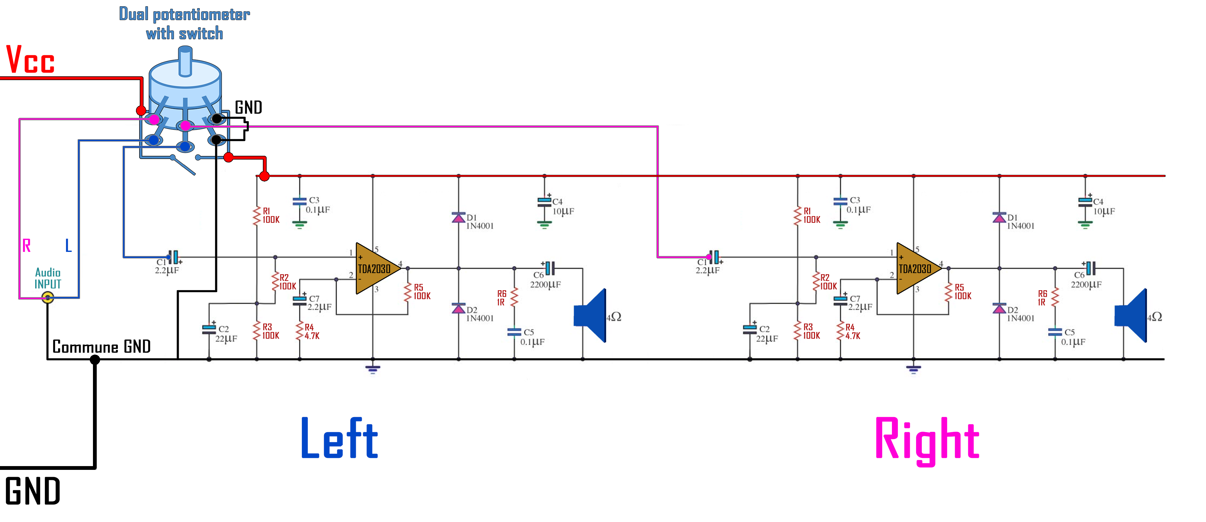
2.0 The circuit
Since there will be two channels this is the final schematic that I will mount. You could download it from below. Make sure you have it in front of you while soldering. Also I recommend you to first try everything on a breadboard and make sure that everything works ok. The full part list, prices and 3D objects are in here.
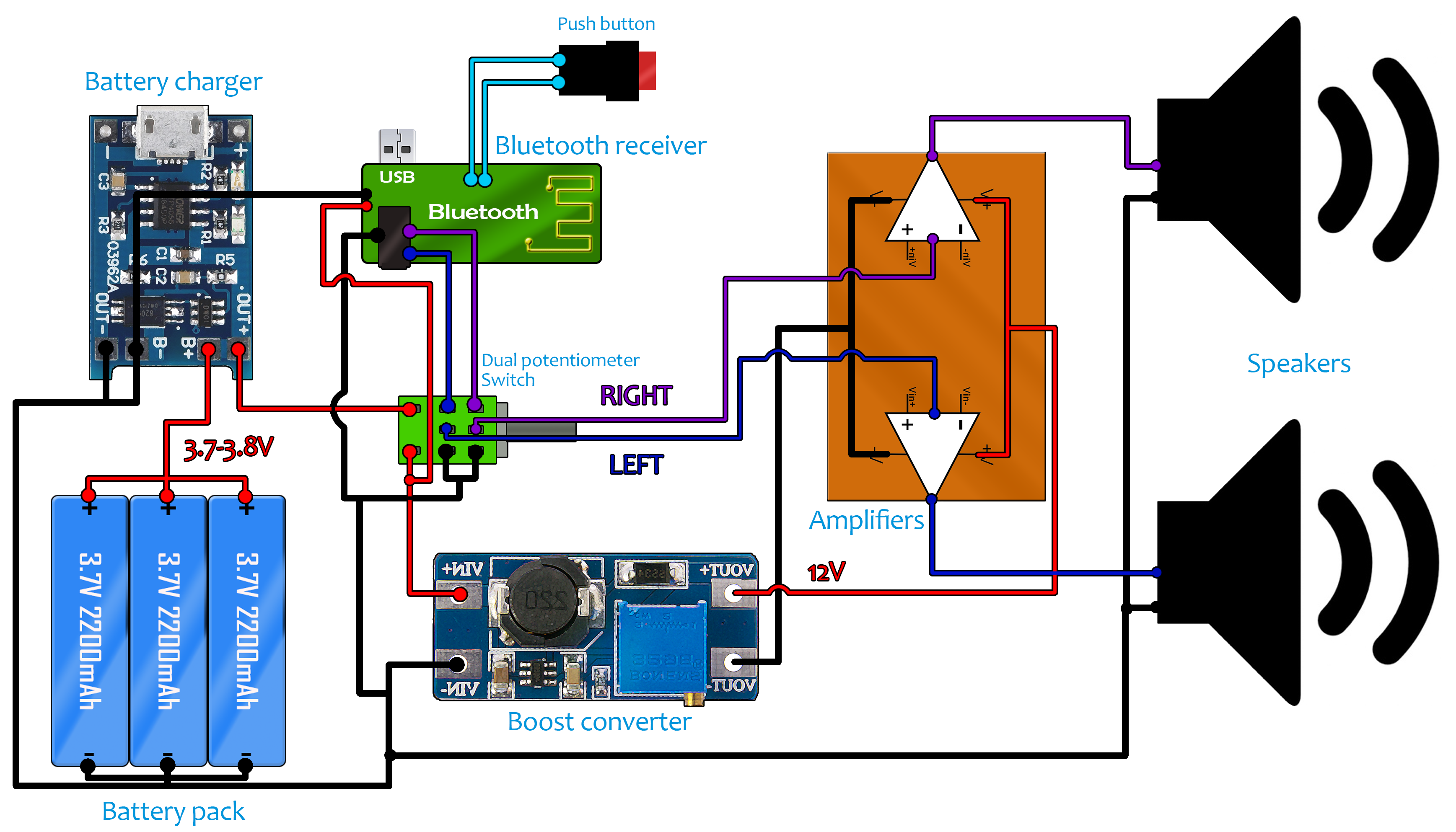
The small and very cheap module could charge a 3.7 volts lithium battery and also protect it of overcharge or discharge. It also have a USB connector so you could charge it using any 5V USB charger or directly from your pc. I take the 3.7 volts lithium batteries and I connect them in parallel to have more capacity. I will charge three batteries in parallel so you might want to use a balance charger. But I won’t do that for this small project in order to keep the price low.
Ok, so you have to connect the charging module to the battery and the output from the charger to the amplifier circuit and to the switch that we’ve talked about earlier. In this way, the batteries could charge but the system will only turn on with the switch. Next, we should increase the voltage for the amplifier to have more power. For that I will use the boost converter module. This will boost the 3.7 volts to exactly 12 volts. For that, using the small potentiometer you can change the output while measuring it with a multimeter. Rotate the potentiometer till you get 12V. If we check the datasheet of the TDA2030 we can see that the maximum input voltage could get up to 24 volts and a maximum output power of 18W. I will leave the voltage at 12 volts to be sure there will be no problems. That should be enough for this project. Look at the full part schematic below. You have two schematics, using both batteries or just one.

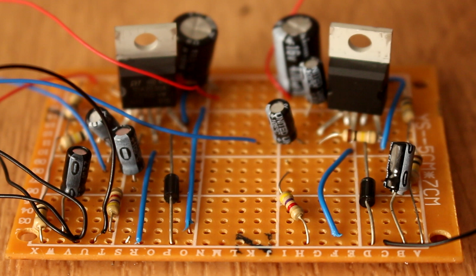
2.1 The amplifier
Using a drilled PCB, I solder all the components following the schematic before. I connect all the components except the volume potentiometer. I start by adding the two amplifiers. Next I add the diodes at the output followed by the 100k resistor between the output and inverted input of the amplifier. I add all the remaining resistors and capacitors and the PCB is ready. Is not the best good looking PCB but it dose the job. As you can see I haven’t soldered the volume potentiometer on the PCB. The reason for that is that I want to be able to screw it on the exterior of the case and then connect it to the PCB circuit. So, for that I solder long wires to between the potentiometer pins and the PCB. I also solder the speakers to ground and the output capacitor of the amplifier.
Now I carefully open the Bluetooth module. I solder 3 wires from the output jack. One is commune ground. The other two are left and right channels. Make sure and double check in order to know which one is which. Solder the wires from the module to the volume potentiometer and from there to the amplifier input, and remember to solder the 4 ohm speakers to the output of the amplifier board. By the way you also have this full schematic with all the components of this project below. The receiver has this small push button that ables you to change the mode when paring the Bluetooth device. Witout removing that small push button I solder two long wires to each side of it. To this wires I connect my own, bigger push button. In this way I could also screw this button to the exterior of the 3D printed case.
The Bluetooth module is also supplied with a 3.7 volts battery. I first removed that and directly connect the 3.7V pack that I’ve added to before. Be careful and don’t connect the boost converter output to the Bluetooth module. That will burn it out. This configuration might work but didn’t for me. I’ve tested the final circuit. At low volume works well. But when I increase the volume, at each sound peak the Bluetooth receiver was restarting itself. I guess that the boost converter draws too much current. I’ve tried and added a big capacitor to the 3.7V output but that didn’t work. The Bluetooth module has a very fine voltage detector that turns it off when it is low. So, I had to add back the small lipo battery that the receiver had separated by the other battery pack. And to charge it I will use the charging circuit that the module already has. For that I just solder two wires from the 5 volts of the battery charging module to the USB input of the Bluetooth receiver. For that I first connect a USB to it and test which is the 5V input. Once I found it, I solder wires between the 5V output of the charging module and the input of the receiver. Now with just one USB I could charge both the 3.7V battery pack and the small battery. As you can see, both charging LEDs are now turned ON. Since the Bluetooth module has a charging circuit, it will stop charging when the small battery is full. But that won’t stop the big battery pack charging process. Maybe this problem is just in case of my receiver. You could try both options. You have both schematics above and below.
Now, as an extra part, I desolder the LED indicators of the charging module and solder two larger LED, one red and the other one blue, same colours as the module has. Using large wires, I could glue these two LEDs also on the exterior of the case in order to know when the battery is fully charged. Now the circuit is ready. We should probably add a heat sink on the back of the amplifiers to keep them cool.
I test it before mounting it inside of the case. I make sure that the batteries are charged, turn on the circuit using the potentiometer switch and establish a Bluetooth connection. Open your smartphone Bluetooth settings and search for devices. Once found connect to it. Now open your music player and press play. The circuit works and sounds quite well for a DIY project and I’m sure that it will sound better inside of a case. Speaker cases are designed to improve the sound acoustics.
So, we have the batteries that are connected directly to charging module and also to the boost converter. The 12V output from the boost converter goes directly to the main switch and from there to the amplifier PCB. Here we connect the audio signal from the Bluetooth module and the speakers at the output. The LED indicators, push button, charging module and volume potentiometer will be placed on the exterior of the 3D printed case. So, let’s mount this speaker.