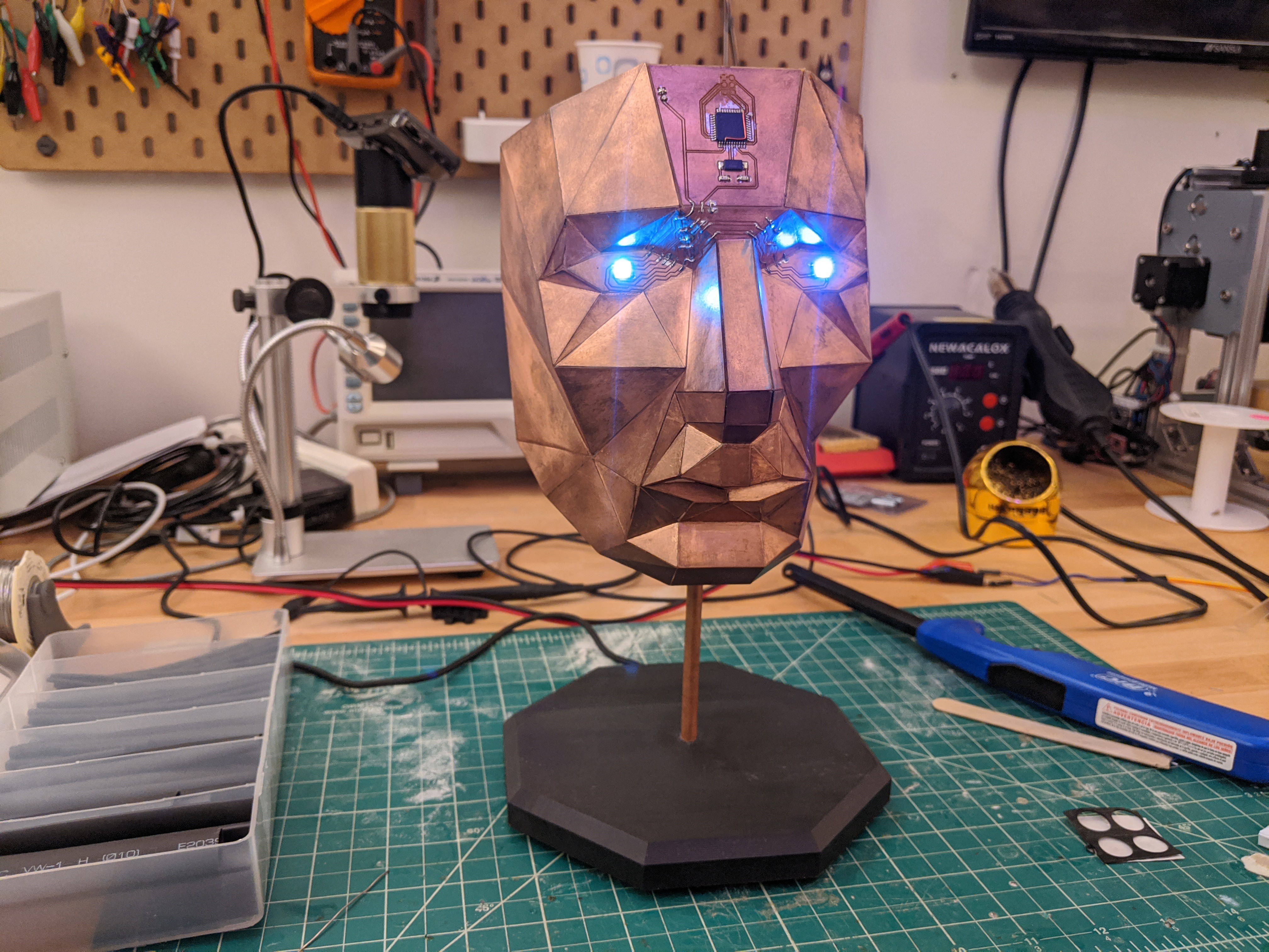
Paper craft has been around almost as long as paper itself. It’s fun to mimic paper craft and origami with low-poly 3D prints, and [Stephen Hawes] wondered whether it could be done with copper-clad PCBs. Two years after the question arose, we have the answer in the form of a fantastical mask with light-up eyes. Check it out in the video here.
[Stephen] started with a model from the papercraft program Pepakura Designer, then milled out dozens of boards. Only a few of them support circuitry, but it was still quite the time-consuming process. The ATMega32u4 on the forehead along with the fold-traversing circuitry serve to light up the WS2812B eyes.
Power runs up the copper tube, which doubles as a handy mounting rod to connect to the 3D-printed base.
To be fair, eighteen months out of the two years this project took was spent hand-sanding a chamfer on every edge of every panel so that they could be glued together.
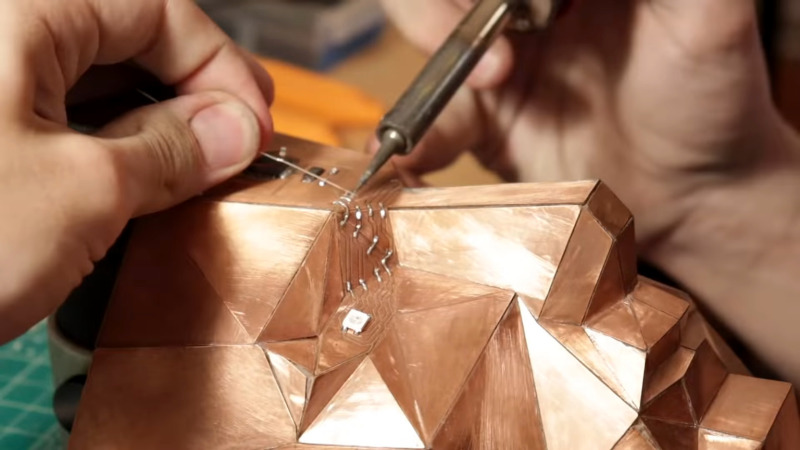
Soldering the edges together didn’t work as well as you might think, so [Stephen] used Superglue mixed with baking soda to give it body and make it dry faster. The result is a low-poly human face of shiny copper with TQFP-44 chip package a the all-seeing eye in the middle of its forehead like something from Tron come to life.
Just a reminder — we have a circuit sculpture contest running now until Tuesday, November 10, 2020 at 12:00 pm PST. We’d love to see what you can do, whether it’s in brass rod, copper clad, or a combination of the two. Take a look at the submissions we’ve received so far, and then show us what you’ve got.
The idea was to use Pepakura (normally used for papercraft) but instead use PCBs. Pepakura takes a mesh and "unfolds" it and adds glue tabs to the panels so you can print it out and make your mesh from paper. I thought it would be cool to do this with circuit boards instead, but also integrate circuitry across the panels of the sculpture!
After I generated all the panels from the 3D model using Pepakura, I imported a few into KiCAD to add a microcontroller and a few LEDs. Then I milled them all out!
What followed was months and months of sanding chamfers into all the resulting panels so that they would meet flush with each other. After glueing up, I connected the traces, programmed the microcontroller, and I'm really happy with the result!