Panel Cookies
yt_link
insta_link
fb_link
twitter_link
Blog#6 - Arduino iron


Last tutorial - homemade soldering iron!
Check here my last tutorial. I hope that you will like it. Keep up you guys!

last tutorial


Arduino based portable soldering iron
Help me by sharing this post

Go back ↞ See other blog→


Author: Andrei
11/06/2018
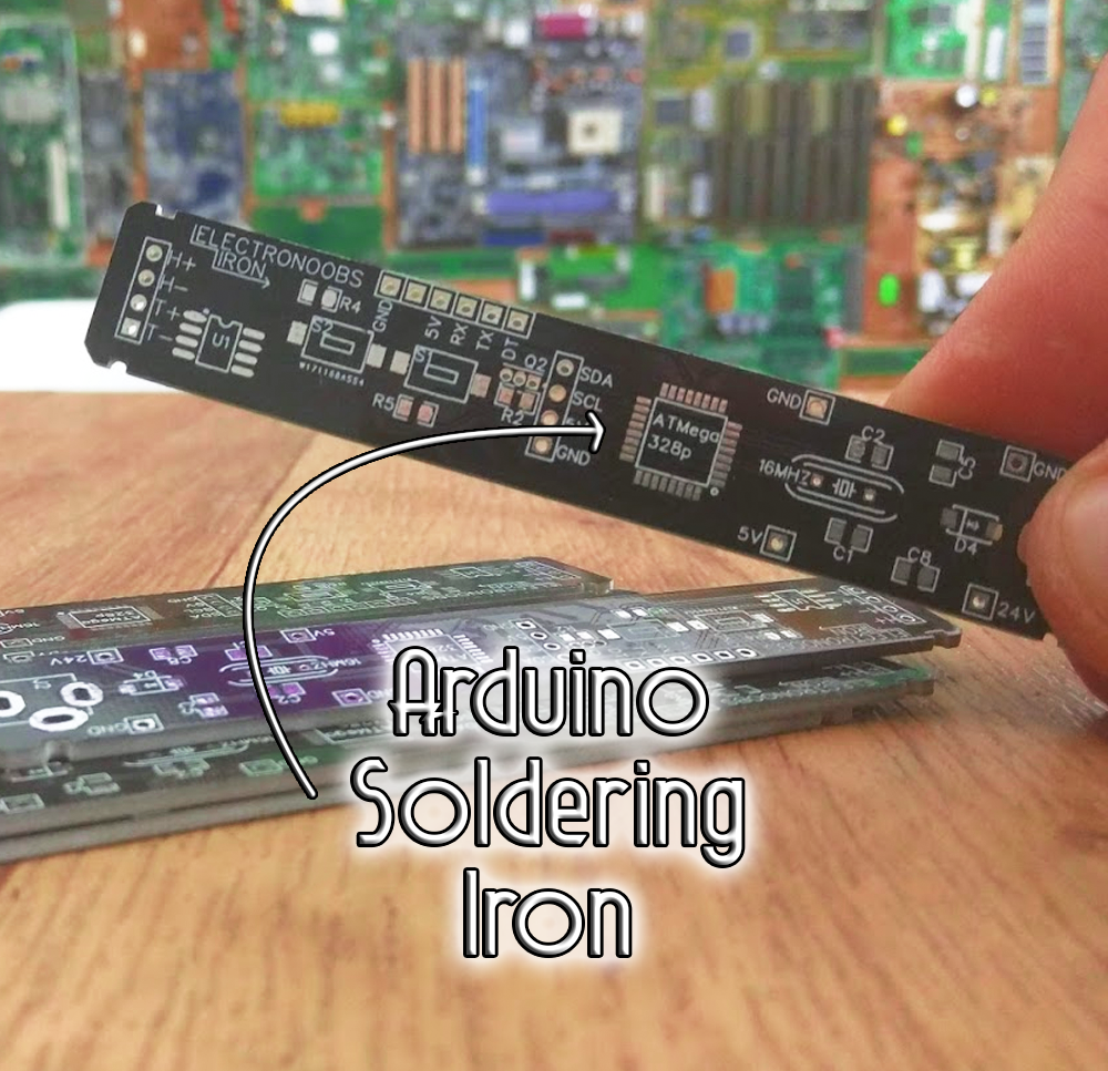
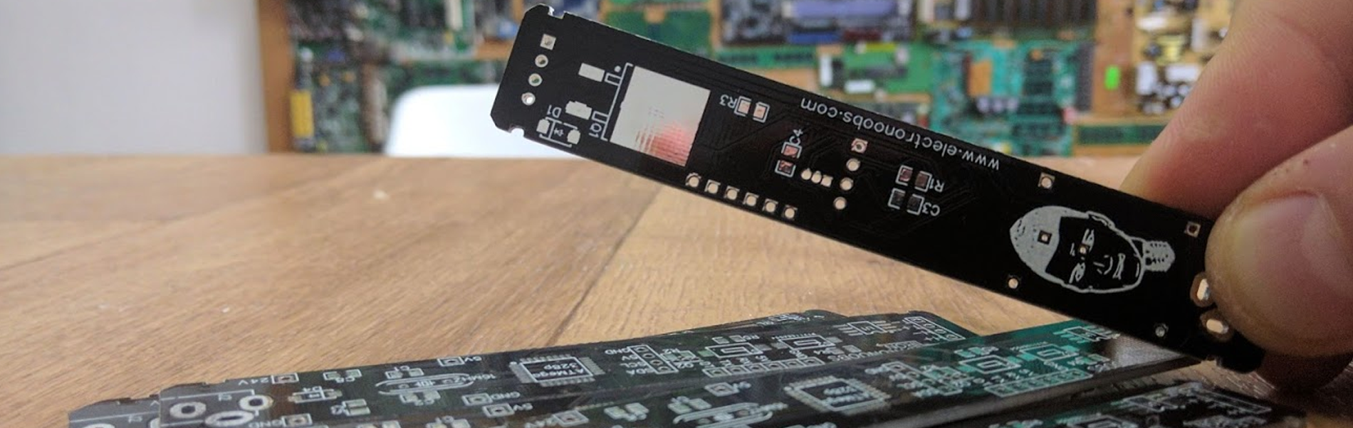
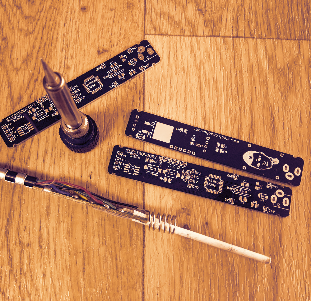
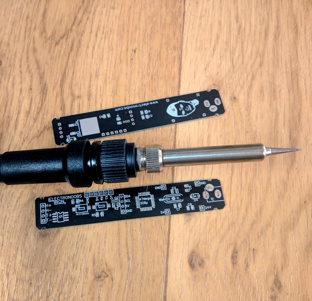
ELECTRONOOBS is on fire. Here we have the PCB he just ordered for his new project. After reviewing the TS100 portable soldering iron, he was amazed of the internal structure simplicity. So, he started designing his own board for a new project, a portable soldering iron. The board looks complicated but it’s quite simple. In the middle, the microcontroller and 4 pins for an OLED screen. That screen has i2c communication so SDA and SCL pins are needed. On the left side, a place for two push buttons can be seen. Those buttons will be used to set the desired temperature. On the left end we can see 4 pins, 2 for the heating element output, H+ and H- and 2 more for the thermocouple read, T+ and T-. The U1 chip is the MAX6675. On the back we have the huge MOSFET for power control. ELECTRONOOBS ordered his design to be manufactured at PCBWay.com and this is the final look.
PID control will eb used for this project. At the output there will be a 24V heater and with a thermocouple inside. The microcontroller will read the temperature real value and create the PID algorithm in order to control a PWM signal applied to the MOSFET. This will control the power applied at the heating element, and by that closing the loop. The main input will be up to 24V so a buck converter is used to obtain 5V for the low voltage components.

The heating element if used from a 6$ 24V soldering iron made for a soldering station. It already has the thermocouple inside and that’s great. ELECTRONOOBS will make the connections between this and his board and he also say he will 3D print a case for the entire iron. The case would have holes for the buttons and OLED screen.

Order PCBs here: PCBWay

The project also needs the solderin iron emtal tip. So, the 3D case will be adapted to the shape of this 24V iron so the metal part could be used. The plastic used in 3D printing won't be heat resistent so part of the plastic cover of the soldering iron will be also used. The tip shape and size could be changed very easy. The heating speed is yet to be known.

So, ELECTRONOOBS will finish this project and post it on his YouTube channel soon. The iron will have a 3D printed case, OLED screen and buttons for temperature control. A power jack for 24V main input and a powerful MOSFET control together with PID for temperature control.

The maximum temperature and speed is yet to be seen after ELECTRONOOBS will finis all the tests. To program the board, an FTDI mdoule is needed since the board has UART port pins. The module would have an USB and by that the board coule be programmed.


Help me by sharing this post


Go back ↞ See other blog→

ADVERTISERS


PCBWAY PCB service


Curso Arduino Online nivel bajo