What’s up my friends, welcome back. Since I’ve reviewed the TS100 soldering iron, I’ve been working on my own portable soldering iron. So, I’ve made some tests, some research, create the PCB and finally made this project. We need a heating element to heat the iron of course. But we also need a thermocouple to read the real temperature value and then create the PID control. But using the thermocouple is not that easy, so we also need a thermocouple amplifier IC. I’ve used the MAX66 75, so I’ve bought the SMD IC so I could place it on my own PCB. This IC has a SPI port so I could communicate with it.
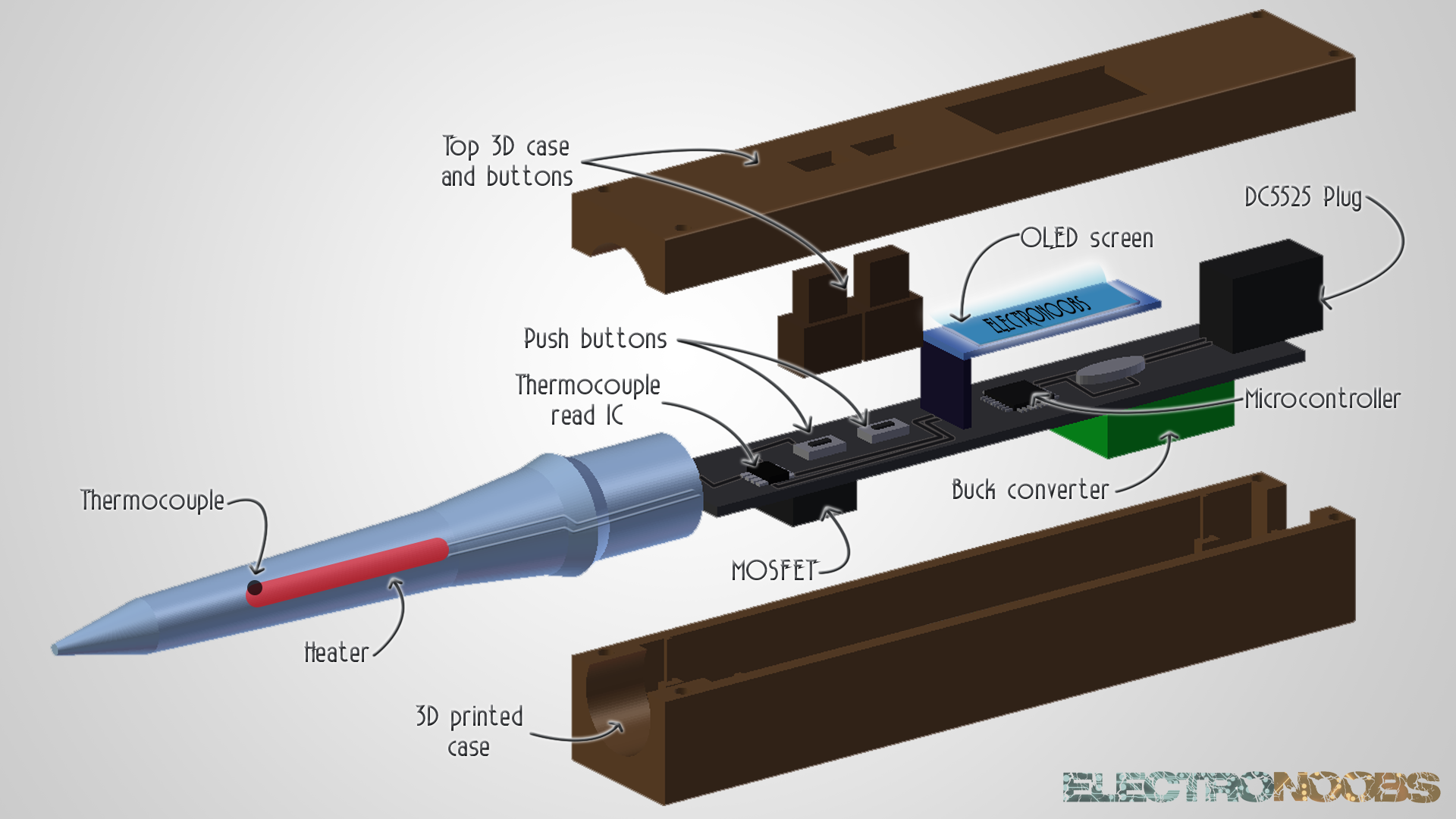
Before we start, let's see what parts will my design have. We need a heater to heat the iron tip. Also a thermocouple to measure the temperature togheter with the MAX6675 IC. Since the entire digital part works at 5V and the main input is from 12 to 24V, we need a buck converter to lower the voltage to 5V. We also need an OLED screen to print the temperature and 2 push buttons for control. The power is controlled with the big MOSFET on the bottom part of the PCB.
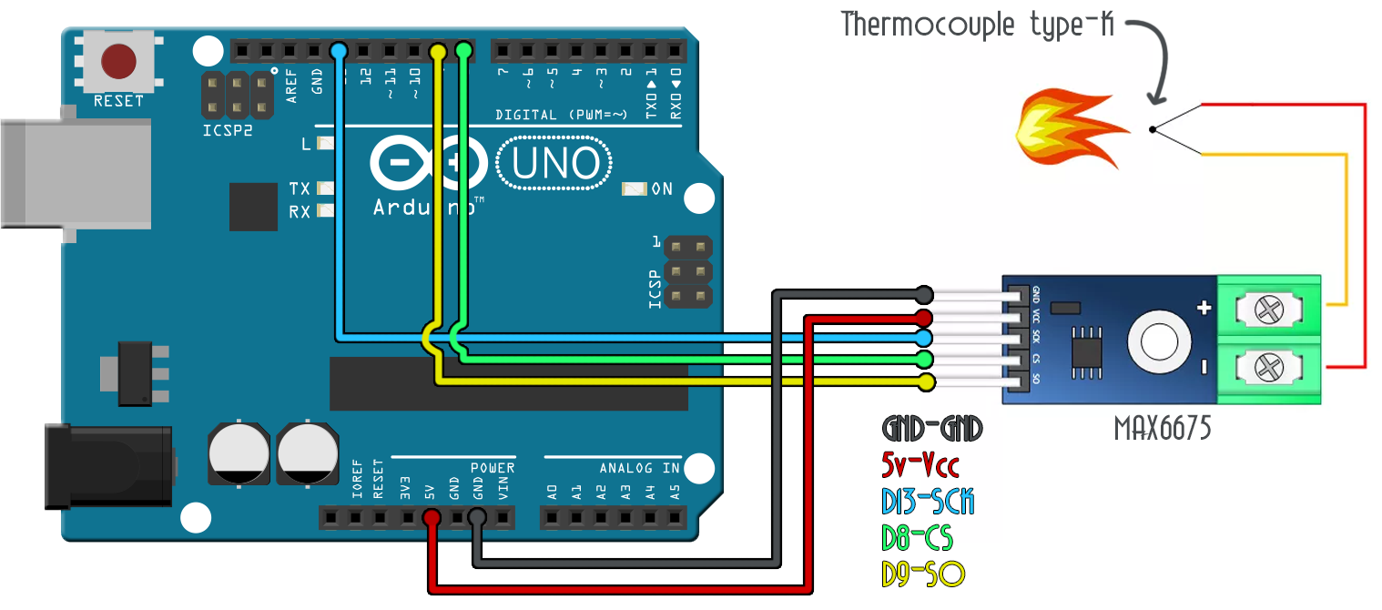
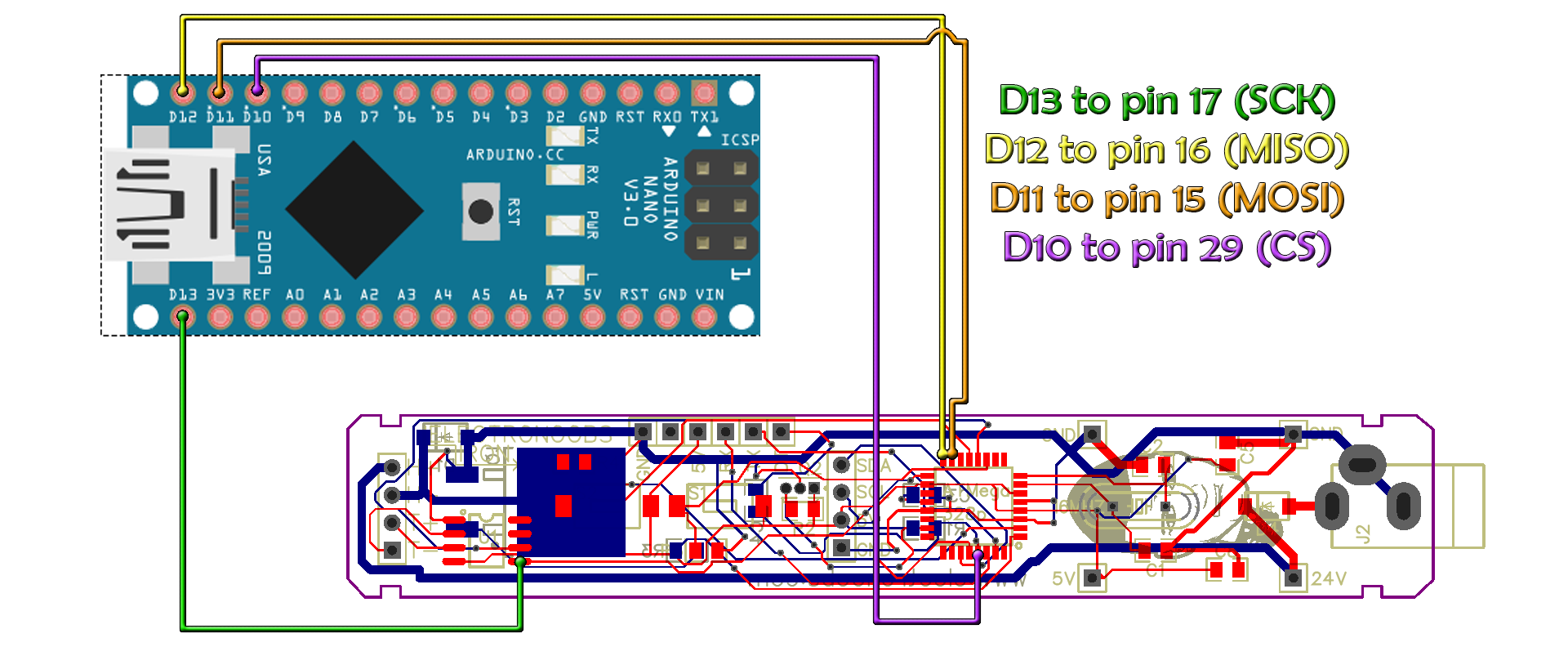
Before we build the entire PCB, let's see how to measure the real temperature. For that we need a thermocouple, the MAX6675 IC and the Arduino. Make the connections below. Be careful, the thermocouple has polarity so positive to positive and negative to negative. Onde you have made the connections, you have to open Arduino IDE:
Now, open the next example code and make sure you install the MAX6675 library. You can alos dwonload the library from below and install it. For that go to sketch, include library, add .ZIP library and open the downlaoded .zip file. You could also use the library manager and search for MAX6675.
Ok, copy the code below and compile.
#include "max6675.h"	//INCLUDE THE LIBRARY

int thermoDO = 9;
int thermoCS = 8;
int thermoCLK = 13;

MAX6675 thermocouple(thermoCLK, thermoCS, thermoDO);

void setup() {
  Serial.begin(9600);
  Serial.println("MAX6675 test");
  // wait for MAX chip to stabilize
  delay(500);
}

void loop() {
  // basic readout test, just print the current temp
   Serial.print("C = ");
   Serial.println(thermocouple.readCelsius());
   Serial.print("F = ");
   Serial.println(thermocouple.readFahrenheit());
   delay(1000);
}
Now, copy the code below and compile in Arduino IDE. If no errors, upload the code to the Arduino using the schematic above and then open serial monitor and set the speed at 9600 baud. Each half second you should have the real temperature printed in both C and F. Heat the thermocouple and see for yourself. The thermocouple
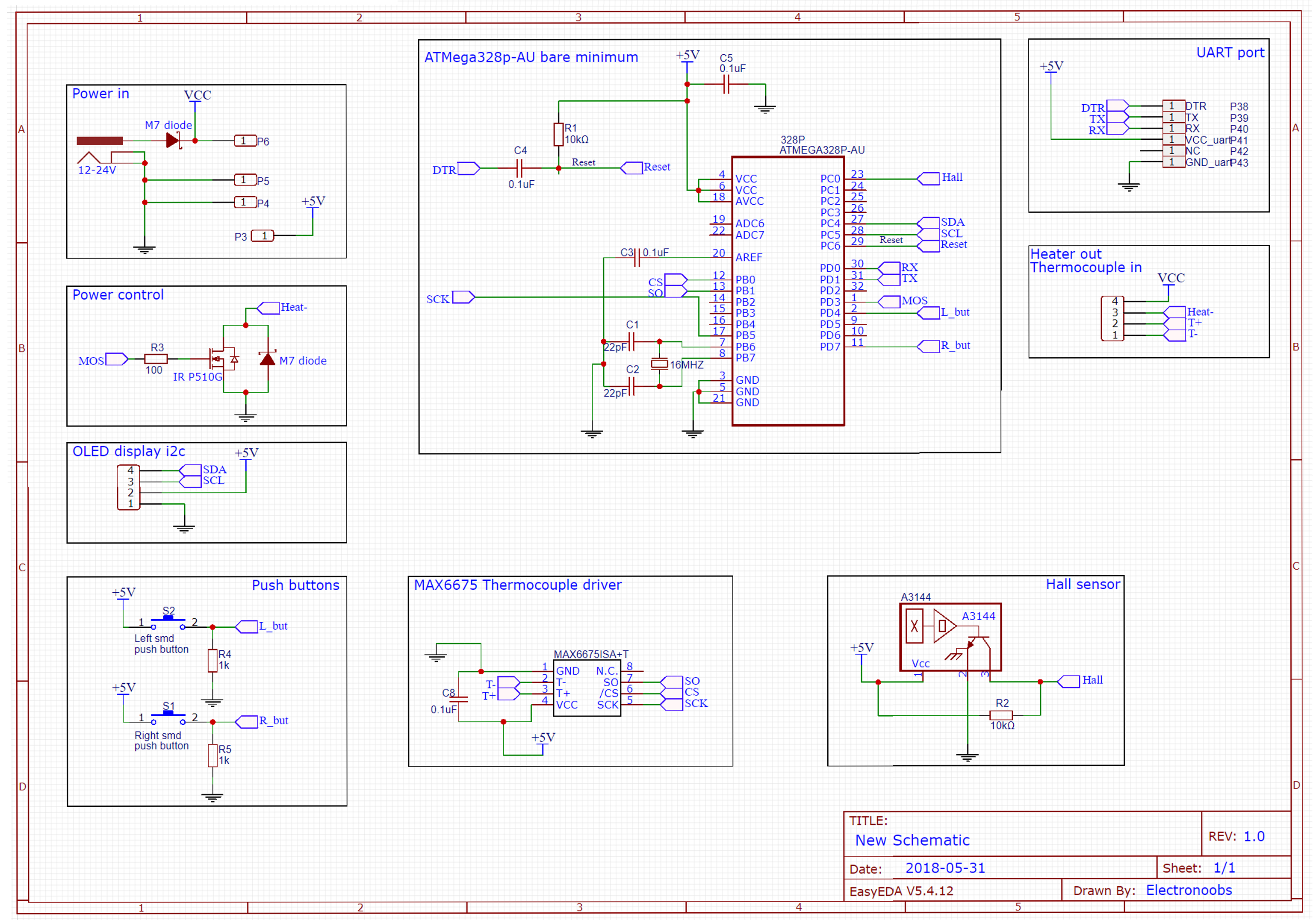
We know how to read the real temperature and we know the parts that the iron needs. With all the components I've made the schematic below. We can see the ATMega328p-AU microcontroller connected to different other components. We haev the MAX6675 thermocouple read IC with SPI communication to the microcontroller. Also, main input plug with the reverse voltage diode, the MOSFET to control the power applied to the heater, push buttons with pulldown resistors, some pins for the UART port and OLED display i2c communication. We also have a hall sensor but that was not used in this tutorial. Finally, there are 4 pins for the heater output and thermocouple input.
Once the schematic was made and I was sure that everything is OK, I've created the layout of the board with a size of 100mm width by 17mm height. I've placed the components as you can see in the layout below with a board of two layers. The uC is on the top layer and the MOSFET on the bottom layer. Alos, on the right, we can see the input of 24V and output of 5V from the buck converter.
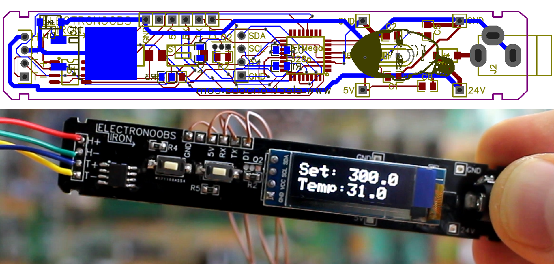
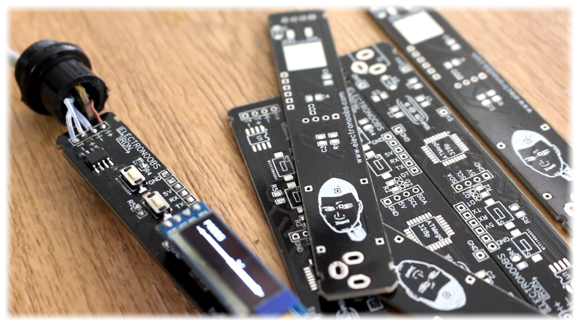
Now, that I have the layout, I copper fill the board and create the GERBERS and send those to JLCPCB and manufacture 10 boards. You can download the GERBER files from the link below and order your own boards.
First thing first, let's mount the bare minimum configuration of the ATMega chip. Below we have the schematic for that. This is the configuration for this chip in order to work. It needs a 5V supply, the crystal of 16MHz and two capacitors of exactly 22pF and a 10K pullup resistor connected to reset pin.

Now, I solder these elements on my PCB. The chip, the crystal, two 22pF capacitors and the 10k pullup resistor and then connect an FTDI module like the one in the photo below to the UART port on the PCB. With these 4 elements we can check if the chip works.

Connect the FTDI to your PC and upload any serial communication test. For example, a code with a Serial.println("HI"); . Open serial monitor and test if it works. If yes, we are good to go.
This part is just in case your chip doesn't have a bootloader. I recommend you to buy one with bootloader or, if not, desolder the chip from an Arduino NANO with a hot air gun and in this way you make sure it will work. Besside, the Arduino NANO has the same price as the chip by itself.
To burn the bootlaoder make the next connections between the baord and an Arduino NANO, SPI connection.
Now open Arduino IDE and connect the Arduino NANO to the PC. Go to FILE → EXAMPLES → ARDUINO ISP and open that example and upload it to the ARduino NANO board. Now, go to TOOLS → PROGRAMMER anc change the programmer type to Arduino as ISP. Finally, go to TOOLS → BURN BOOTLOADER and the LEDs will start blinking fast. Once you get the message bootloader burned, you are good to go. Change back the programmer type and connect the FTDI module and upload a test code.
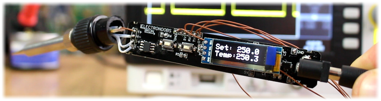
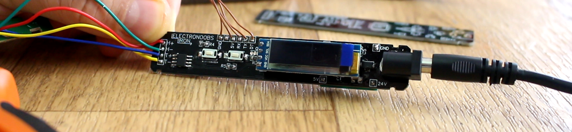
Now, let's solder all the parts but the buck converter. Once all the parts are soldered, the OLED screen, the MOSFET, the MAX6675 IC, all the resistors and capacitors and the input plug, here is what you have to do.
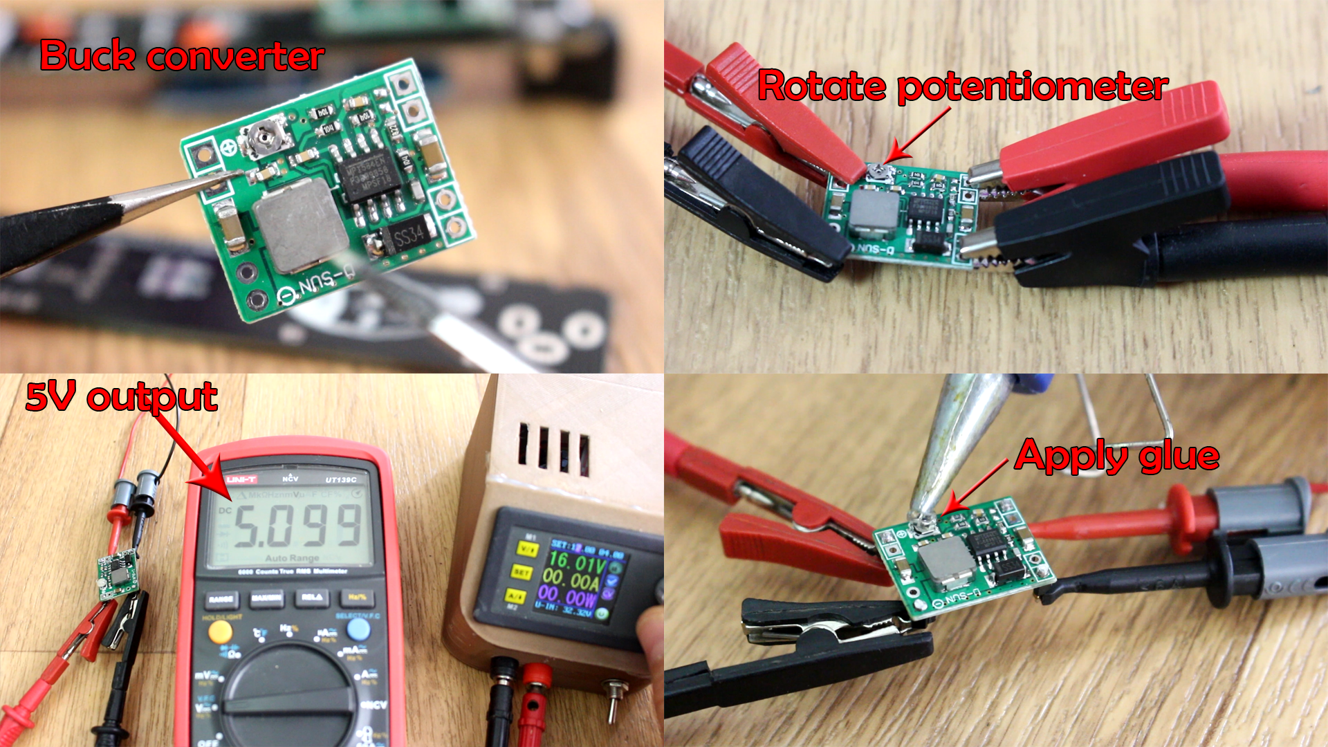
Now, take the buck converter and supply 12V to 24V to it and rotate the potentiometer till you get around 5 or 5.1V at the output. Now, place hot glue on the potentiometer so we make sure it won't move by mistake and bur our microcontroller and the entire board.
Now we have the 5V. We can solder the buck converter to the board and next step is to solder the heater and the thermocouple to the H and T pins. For that, first we have to know which are the positive and negative pins of the thermocouple.