
 About me
  History
  Let's learn
  Contact us
  Arduino tutorials
 Circuits tutorials
  Robotics tutorials
 Q&A
Q&A Blog
Blog  Arduino
  Circuits
 Robotics
  Modules
  Gadgets
  Printers
  Materials
  3D objects
  3D edit
  Donate
  Reviews
  Advertising


Optic encoded precise step motor (3D printed)
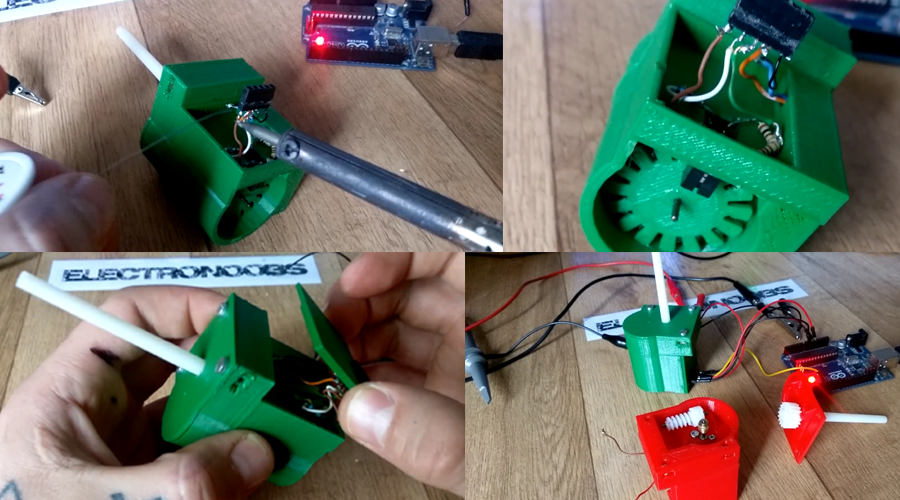
Building the case
Okey so now we can encode the rotation of our small DC motor. But it spins quite fast for a step motor. Besides, spinning that fast won't give us any precision. For that we should add a small gear system to the design. Also I want to make this motor to have the exact size and screw position as the NEMA17 witch is one of the most commune step motor in CNC machines. I've used this turbine motor to pull out the worm gear system and 3D designe my own case for the motor.
The 3D design
Okey so I've designed my object in blender. After 14 prototypes I've decided that this is the best one. The case is divided in 5 parts that we will have to glue uisng super glue. Okey so first we screw in place the small DC motor with the work gear inside of the part "1".
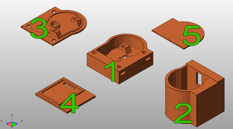
Once the DC motor is screwed in place we can glue together part "1" and "2". The enxt step is to add the optic switch circuit inside of the side hole of part "2" with the optic sensor inside of the case. At the same time we should add the 32 steps disc on the shaft of the motor and make sure that it is in the middle of the optic switch.
Finally we add the worm gear and close the case. Add the screw nuts and glue all the parts of the motor. We add 5 female pins on the side of part "4" and solder to those 12V and GND for the DC motro and 5V, GND and output for the optic switch. Our optic encoded motor is ready.
Copy or download the next text code. That code will allow you to give a certain angle and the motor will spin back and forth that amount of degrees. If each rotation is 32 steps multiplied by the gear ratio we have a total of 6400 steps per rotation or 360 degrees.