
 About me
  History
  Let's learn
  Contact us
  Arduino tutorials
 Circuits tutorials
  Robotics tutorials
 Q&A
Q&A Blog
Blog  Arduino
  Circuits
 Robotics
  Modules
  Gadgets
  Printers
  Materials
  3D objects
  3D edit
  Donate
  Reviews
  Advertising


Optic encoded precise step motor (3D printed)
As you know a basic step motor could be quite expensive. Step motor are used because of their high precision and step by step control. A step motor also requires a small step motor controller module in order to work. We can't connect the motor directly to a microcontroller because it won't give us the required amount of current in order to spin the motor. A step motor driver receives some signals with the directions and amount of steps to do. It controls 4 outputs to the step motor and spin the motor in the desired direction and the desired amount of steps. A pretty decent step motor could cost around 20 euros and the driver from 3 to 5 euros as well.
Today I want to show you a different way to implement a step motor. In a normal step motor we know the amount of steps that we whant to make and send that amount to the driver. In this project we know the amount of steps that we want to do but we don't send that amount to the motor. Instead, we activate the motor and count the steps that it dose till we reach the desired amount. Sounds easy right?
The encoder
So first we are going to build the encoding system. As it name tells us, an encoder is a device that encodes information. If we take a look at the definition of encode we can see that it could also mean the action of converting one system of communication in to another. In our case we are going to convert angular motion into digital pulses using an optic switch.
So I have this next MITSUMI DC motro that can reach up to 14000rot/min at 12V. What I want to achieve is to precisely control it’s rotation, it’s speed and position. So for that I design and 3D printed the next disc.
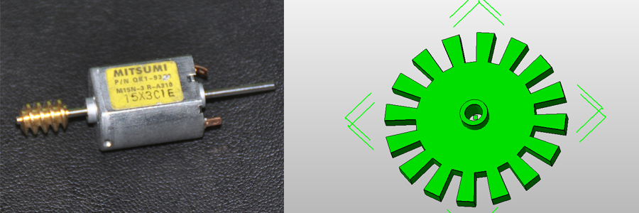
As you can see the disc has 16 holes and 16 teeth. If there would be a way to count the holes in the disc while rotating, then I would know that each 16 detected holes I’ve got a full rotation of the shaft. Or even more, if there would be a way to detect both holes and fills I would know that each 16 holes and 16 fills I’ve got a full rotation. And that would give me even more precision. So the next element that we need to complete our encoding system is a device that would be able to detect this steps on my disc. For that I will use an optic switch.
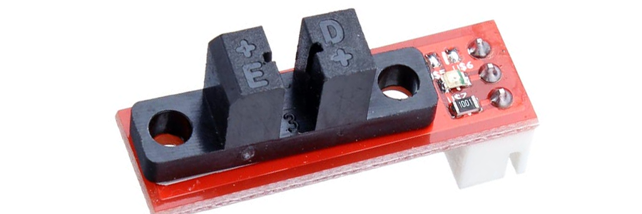
A basic optic switch works like this. It must have two elements. One is the transmitter which in this case is an infrared light LED, and the second element is the detector which in my case will be a phototransistor. This phototransistor is like a normal BJT transistor but it’s base is exposed to the light. This is a light sensible base and works like this. When light touches the base of this transistor the collector to emitter circuit is open and the transistor doesn’t allow current to flow through it. When no light touches the light sensible base, current is allowed to flow from the collector to the emitter. So basically our phototransistor works like switch that is open with light and closed in darkness or vice versa. But, to avoid normal visible light to affect the circuit, we use a infrared sensor. This type of transistor will activate only with infrared waves. That’s why we use a infrared led diode.
The circuit
First we put the infrared diode face to face with the phototransistor with the drilled disc that I’ve designed before in the middle. In this way when we have a hole in the disc, light can pass and open the circuit of the sensor and when we have a fill, light won’t pass and the phototransistor circuit remain closed. So just that easy we are able to detect the holes and fills on our disc.
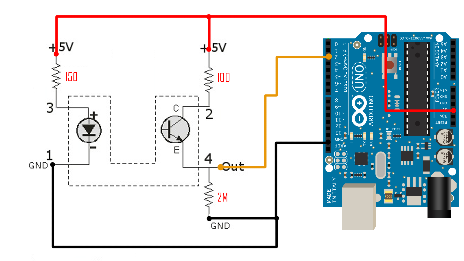
Be careful, the diode resistor must never be lower than 100 ohms or at 5V the diode could burn. We connect the output of the switch to digital pin 2 of the Arduin. Using the digitalRead function we could detect HIGH and LOW states of the input. Uisng the configuration in the schematic above, I've managed to obtain a low value of 0 volts and a high of 5 volts which is perfect.
Now we have to make a small code in order to count the steps. We will detect a step both on holes and fills of the drilled disc that I've designed. Each variation from a hole to a fill or vice versa will be interpreded as a step.