About me
  History
  Let's learn
  Contact us
  Arduino tutorials
 Circuits tutorials
  Robotics tutorials
 Q&A
Q&A Blog
Blog  Arduino
  Circuits
 Robotics
  Modules
  Gadgets
  Printers
  Materials
  3D objects
  3D edit
  Donate
  Reviews
  Advertising


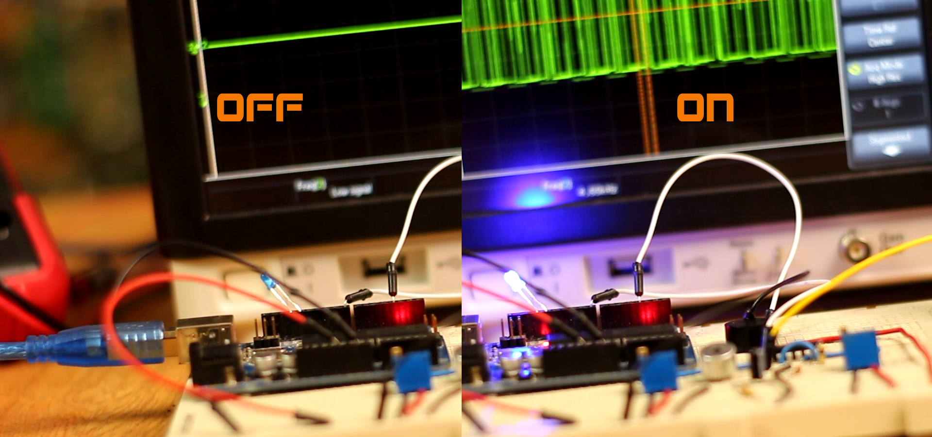
LED and buzzer whistle switch
Download the .zip file below. Unzip it and open it in Arduino IDE. Compile and upload.
/*Whistling sound switch; author: ELECTRONOOBS
* Subscribe: http://www.youtube.com/c/ELECTRONOOBS
*
* Activate any Arduino loop just by whistling. The circuit is very easy.
* Check the entire tutorial here: http://www.electronoobs.com/eng_arduino_tut19.php
*
*
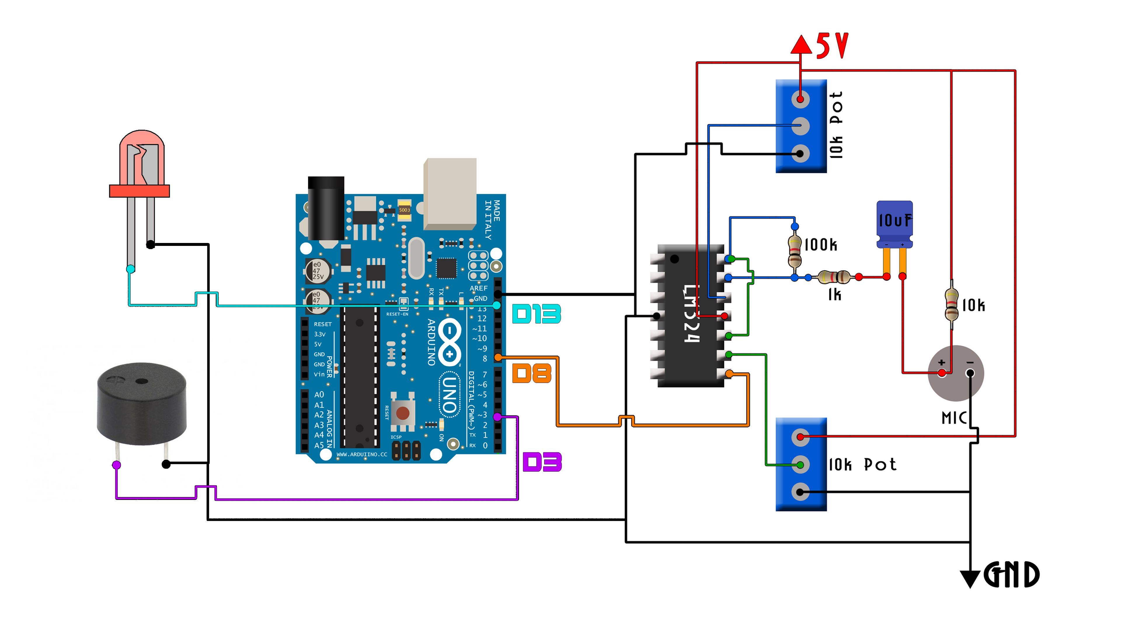
* Input pin is D8
* Relay output is D13
* PWM buzzer output is D3
*/
//Inputs/outputs
int LED = 13;
int buzzer = 3;
//We create a variable for the time width value of the input signal
unsigned long last_pulse_time_counter, present_time;
//We create 1 variables to store the previous value of the input signal (if LOW or HIGH)
byte last_PIN_state;
//To store the final width value we create this variables (this will be half of the period)
int Pulse_width;
//Variables
float Period = 0;
float Frequency_micro = 0;
float Frequency = 0;
int Pulse_amount = 0;
int pulse_is_measured = 0;
bool LED_Status = false;
void setup() {
/*
* Port registers allow for lower-level and faster manipulation of the i/o pins of the microcontroller on an Arduino board.
* The chips used on the Arduino board (the ATmega8 and ATmega168) have three ports:
-B (digital pin 8 to 13)
-C (analog input pins)
-D (digital pins 0 to 7)
//All Arduino (Atmega) digital pins are inputs when you begin...
*/
PCICR |= (1 << PCIE0); //enable PCMSK0 scan
PCMSK0 |= (1 << PCINT0); //Set pin "D8" trigger an interrupt on "any" state change.
pinMode(LED,OUTPUT);
digitalWrite(LED,LOW);
pinMode(buzzer,OUTPUT);
digitalWrite(buzzer,LOW);
//Start the serial in order to see the result on the monitor
//Remember to select the same baud rate on the serial monitor
Serial.begin(250000);
}
void loop() {
/* Ok, so in the loop the only thing that we do in this example is to print
* the received values on the Serial monitor. The PWM values are read in the ISR below.
*/
if(pulse_is_measured) //Only when a full pulse is measured we enter the loop
{
pulse_is_measured = 0; //We reset "the pulse is detected" for the next loop
Period = Pulse_width*2; //Multiply by 2 the width and obtain the signal period
Frequency_micro = 1/Period; //Invert the period and get the frequency (in Hertz by us)
Frequency = Frequency_micro*1000000; //Multiply by one million and get frequency (in Hertz by seconds)
if(Frequency > 800 && Frequency < 1800) //Detect the frequency range. Change the values for your range
{
//Serial.print("Freq: "); //Only uncomment this for tests. This will add extra delay to the loop
//Serial.print(Frequency);
//Serial.println(" ");
if(Pulse_amount >= 60) //I want 60 detected pulses with the same frequency range in a raw to
{ //be detected before I activate the output.
LED_Status=!LED_Status; //We invert the relay output (turn on or off)
digitalWrite(LED,LED_Status); //We write the relay status to the pin.
analogWrite(buzzer,230);
delay(200);
analogWrite(buzzer,LOW);
delay(200);
analogWrite(buzzer,230);
delay(200);
analogWrite(buzzer,LOW);
delay(200);
analogWrite(buzzer,230);
delay(200);
analogWrite(buzzer,LOW);
delay(1000); //Add a small delay so we won't detect two whistles one after another
Pulse_amount=0; //Reset the detected pulse amount
}
Pulse_amount = Pulse_amount+1; //Increaase the pulse amount by one in each loop only if the range is correct
}//end of frequency range detect
else
{
Pulse_amount=0; //If the range is not correct, we have an error so we start from the beginning. Reset the amount value.
}
}//end of if pulse is measured
}//end of loop
//This is the pulse width interruption routine
//----------------------------------------------
ISR(PCINT0_vect){
//First we take the present_time value in micro seconds using the micros() function
present_time = micros();
///////////////////////////////////////Signal input
if(PINB & B00000001){ //We make an AND with the pin state register, We verify if pin 8 is HIGH???
if(last_PIN_state == 0){ //If the last state was 0, then we have a state change...
last_PIN_state = 1; //Store the current state into the last state for the next loop
last_pulse_time_counter = present_time; //Set pulse_time_counter to current value.
}
}
else if(last_PIN_state == 1){ //If pin 8 is LOW and the last state was HIGH then we have a state change
last_PIN_state = 0; //Store the current state into the last state for the next loop
Pulse_width = present_time - last_pulse_time_counter; //We make the time difference. Channel 1 is current_time - timer_1.
pulse_is_measured = 1; //We indicate that one full width was measured
}
}