This project is for a homemade chronograph and this device is used to measure muzzle speed which basically is the speed of bullets. If you remember, a few weeks ago I’ve made a coil gun project, which by the way was very powerful and I recommend you to watch that video as well. Anyway, if I want to know the speed of that metal projectile, I need such project. Basically, this device will measure the time between the input and output of the bullet and will give us the speed in meters per seconds. Is a very easy to make project, but I hope you will learn something new. I will show you what we need to make it, the schematic, the code, how to assemble everything and then we will test it out and see if it works. So guys, let’s get started.
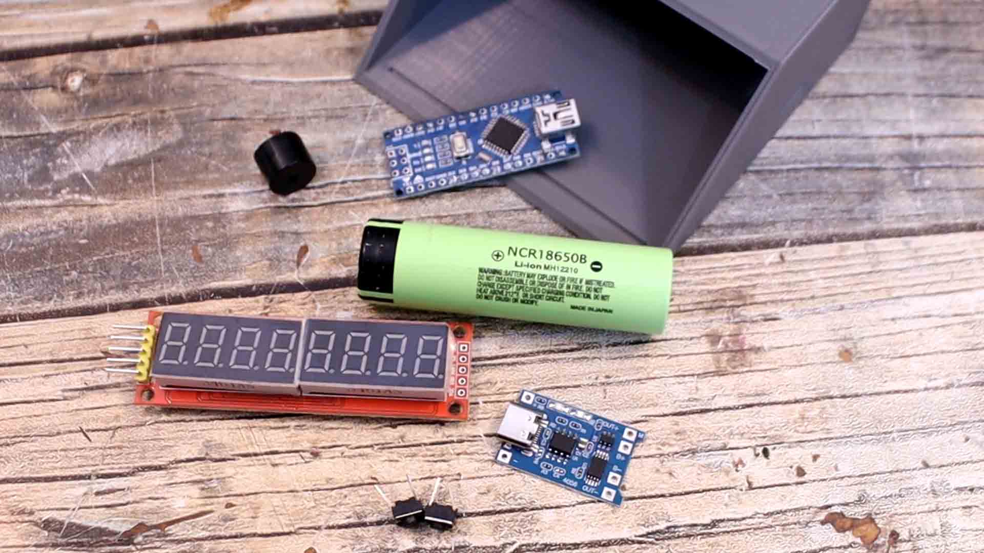
My first idea was using lasers, one LDR sensor and mirrors. But the mirrors were absorbing the light from ther lasers too much. So at the end of the beam, the LDR wasn't receiving any more light. So I had to change my idea. We need a series of around 7 LDRs connected to a comparator module. THis will give a HIGH oir LOW output to the Arduino. We need the lasers, the 3D printed files, a battery and a charger and wires. We also need a 7 segment display to show the speed. Check the list below.
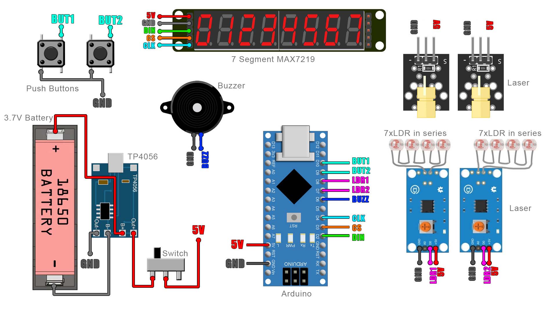
This is the schematic for the project. Just the sensors connected to the Arduino, the battery for supply and the display to show the speed value. First we solder the charger to the battery. Then, between the battery and the circuit I add a switch so we could turn the circuit on and off. This switch will power the Arduino which is connected to the sensors, the buzzer and the display. The 5V connection is actuall 4.2V from the battery but that's enough for the Arduino to work ok. Make all connections as below.
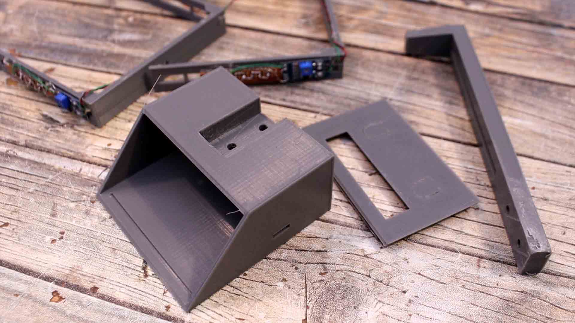
Download the files from below. We need 5 parts. The main case and the case top, the long leg and two supports for the laser and the LDR sensors. Print the support with PLA material, 20% infill and 2 perimeters. You don't need to use supports.
Solder 7 LEDs in series. We connect them to the comparator module. THen we glue them to the side of the 3D printed support. Remove the lens from the laser module and glue iut in front of the LDRs on the other side of support. We set the potentiometer later. I first solder the charger to the battery. Then, between the battery and the circuit I add a switch so we could turn the circuit on and off. This switch will power the Arduino which is connected to the sensors, the buzzer and the display. Now all connections are made with thin wires so before we add this all inside the 3D printed case, we should give it a test. Download the code from below and upload it to the Arduino.
If we take a look at the code we can see that we have the sensor pins defined on pin 8 and 9. Using interruptions we detect when the first sensor is triggered and we save the time value. Then we detect the second sensor and we equal the time to the difference between the actual time and the previous time. This will be in microseconds so we divide it by 1 million so we get seconds. Then we divide the distance between the sensors by that time value. By the way you should manually measure the distance between the sensors with a rouler. Then get in the code and change that value according to your distance. We get the speed and we divide it in digits and print those to the seven segment display. That’s it for the code.
//Pins of the 7 segment display
#define MAX7219_Data_IN 2
#define MAX7219_Chip_Select  3
#define MAX7219_Clock 4

//Inputs/Outputs
int but_1 = 10;                 //Left button
int but_2 = 11;                 //Right button
int sensor_1 = 8;               //Front sensor
int sensor_2 = 9;               //Rear sensor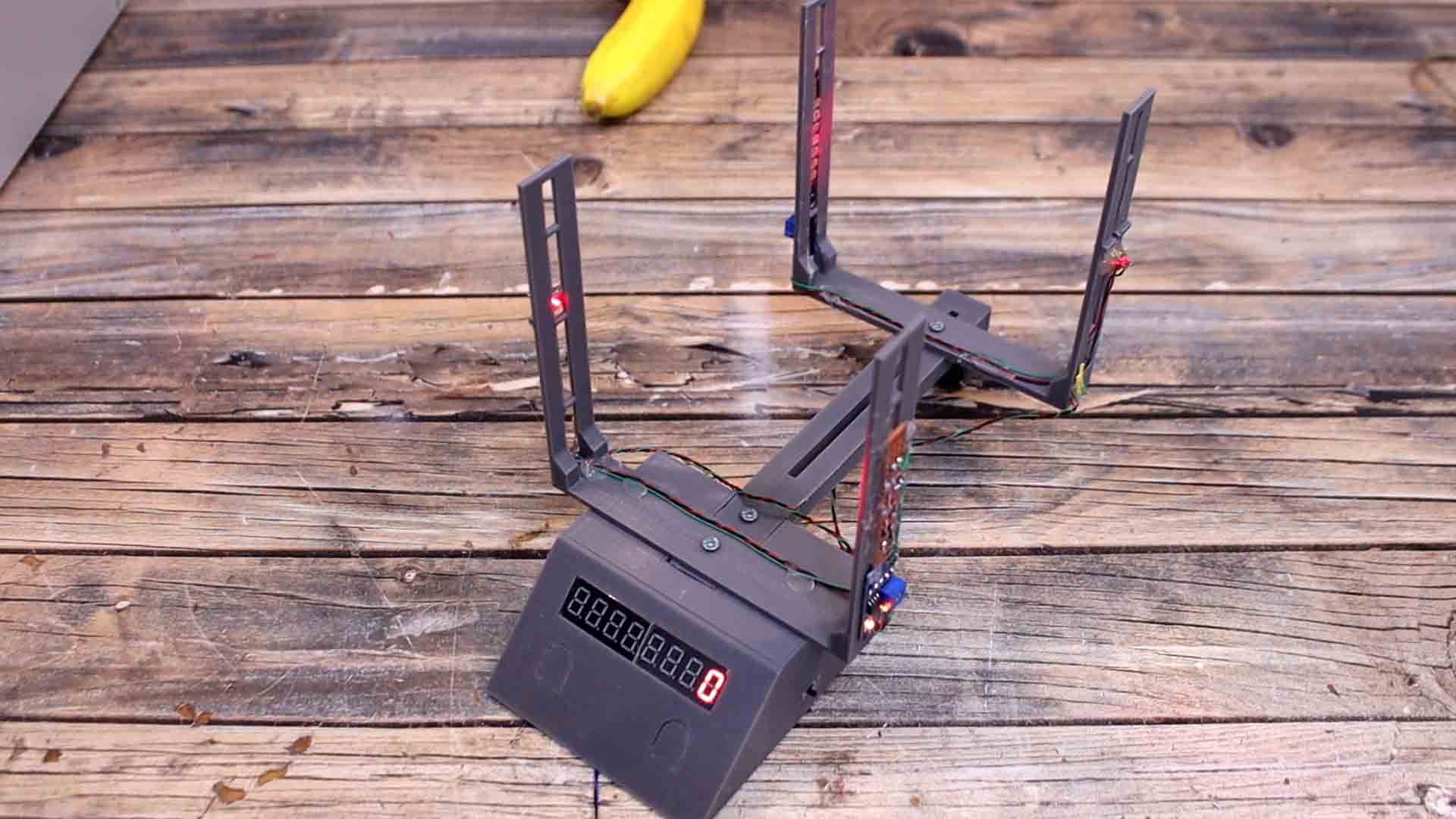
int Buzzer = 6; //BuzzerMake sure you adjust the sensors again using the potentiometers till they can detect the bullet. Let’s test it with my coil gun from the other project. I power it on and charge the capacitors above 400V. Make sure the meter is reset and I fire the bullet. Amazing, I get a speed of 128 m per seconds. I reset the meter and fire it again but I charge the capacitors a bit more. This time I get 139m/s and that’s amazing, because have in mind the average speed of firearms bullets can go between 120m/s for old muskets up to 1200m/s for now days rifles. So the speed of my coil gun is far from those but even so, is quite dangerous and it could harm you so be careful if you make that same project.
So guys, this was a simple project. There are multiple ways to make this. You have mi circuit, the part list, the 3D printed files and my code above in case that you want to make the same project. I hope that you have learned something new. If my videos help you, consider supporting my work on my PATREON or a donation on my PayPal. Thanks again and see you later guys.