
 About me
  History
  Let's learn
  Contact us
  Arduino tutorials
 Circuits tutorials
  Robotics tutorials
 Q&A
Q&A Blog
Blog  Arduino
  Circuits
 Robotics
  Modules
  Gadgets
  Printers
  Materials
  3D objects
  3D edit
  Donate
  Reviews
  Advertising


Arduino Bluetooth controled 8x32 LED matrix
Schematic ATmega328
We've seen the schematic for an Arduino UNO. But I want to use the ATmega328 chip directly on to a PCB. For taht we have to add the chip and all the extra components that make the microcontroller work such as the crystal oscilator and the oscilating capacitors. Also we have to add a 5V voltage regulator.
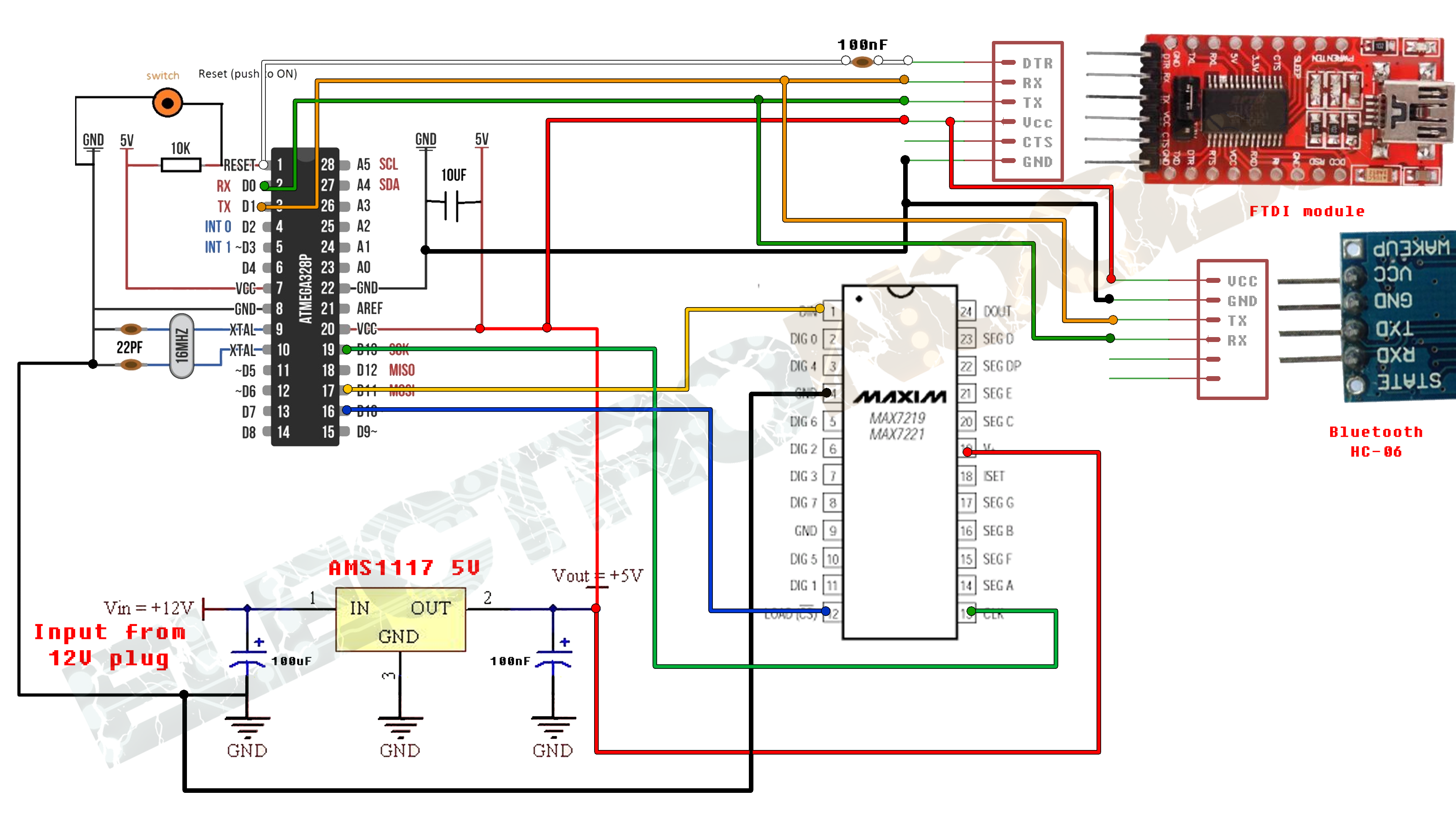
As voltage regulator I've used the AMS1117 5V voltage regulator with two capacitors to filter the noise. We add 6 female pins for the FTDI module.
Programming the ATmega328
If you use the Arduino UNO or NANO just download the code below and upload it to the Arduino. Remember to disconnect the Tx and Rx pins from the bluetooth module while uploading the code.
If you use this same ATmega328 on a PCB you have to make sure that it already has a BOOTLOADER burned to it. If you want to see how to burn a bootloader to an ATmega chip just check my next video.
Now that the atmega chip has the bootloader we can upload the code using the FTDI module. Connect the FTDI as shown in the schematic above. Open Arduino IDE and open the next code:
The code:
You should also dwonload the
To install open Arduino IDE, go to sketck, add library, add .zip library and open the downlaoded .zip file.