
 About me
  History
  Let's learn
  Contact us
  Arduino tutorials
 Circuits tutorials
  Robotics tutorials
 Q&A
Q&A Blog
Blog  Arduino
  Circuits
 Robotics
  Modules
  Gadgets
  Printers
  Materials
  3D objects
  3D edit
  Donate
  Reviews
  Advertising


Arduino Bluetooth controled 8x32 LED matrix
This will be an awesome tutorial. We will create our App using AppInventor tool. If you want to see step by step how to create your own just match
Material
1 x Arduino (NANO or UNO)
1 x Bluetooth module HC-06
256 LEDs (I've used 10mm)
4 x MAX7219 LED matrix drivers
2 x 100x40 cm wood board
1 x ams1117 5V voltage regulator
1 x 10uF capacitor
1 x 100nF capacitor
1 x 12V transformer
Drilled PCB, connectors, solder, wires, tools, etc...
Schematic -Arduino UNO
We have to create 4 matrices eacho of 8 by 8 leds. Each MAX7219 driver can handle a 64 LEDs matrix. The arduino will send the data using a serial comunication. So we have to connect the clock and load pins from the arduino to all MAX7219 drivers. The data pin will be only connected to the first driver. From the "data out" pin of the first driver we will connect a wire to the second "data in" of the second driver and so on. That's how we connect four 8x8 matrices in serie. We should also connect the bluetooth module to the Tx and Rx pins of the arduino and supply 5V to it and to each of the MAX7219 drivers.
First let's take a look on how to connect each of the 8x8 martices. Once we have our 4 matrices we can join them together with the "data out" "data in" pins.
![]()
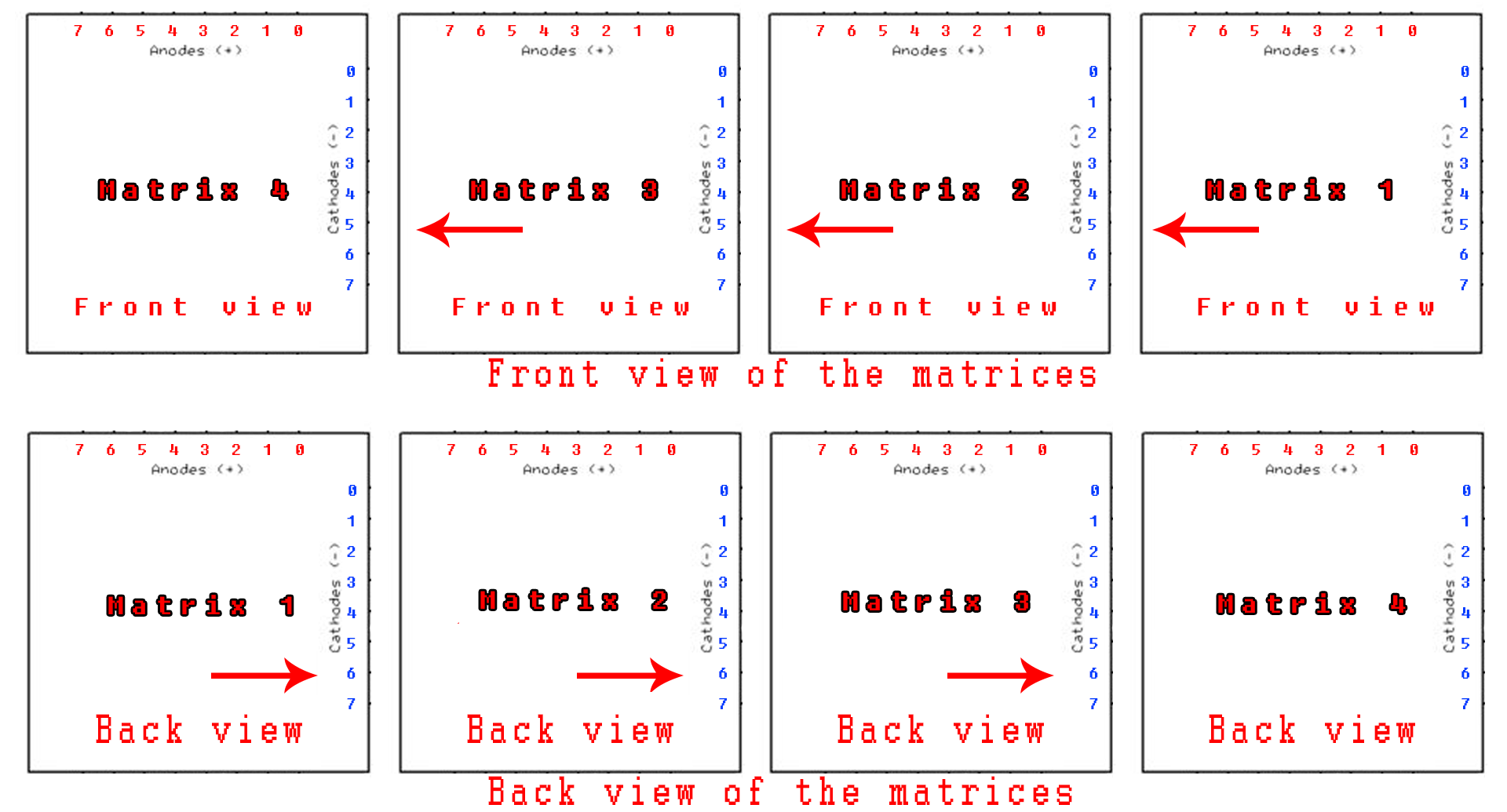
In the above schematic you can see how to join one 8by8 LED matrix. We have to create 4 matrices in the same way. Once we have our 4 matrices we connect the data out from the first to the next data in and so on. The load and clock is the same for all matrices. As you can see in the schematic above, it shows the back view. The arrow shows the direction of the next 8by8 module. You can see the final circuit in the schematic below.
![]()
In order to not get lost, let's take a look at the fron side of the entire 32by8 matrix in the picture below. You can see that now the arrow pints the oposite way than in the previous modulke scheamtic. That's because we've flipped the modules and we can see the front side. So the text will scroll from right to left, from the first 8 by 8 matrix to the forth one.
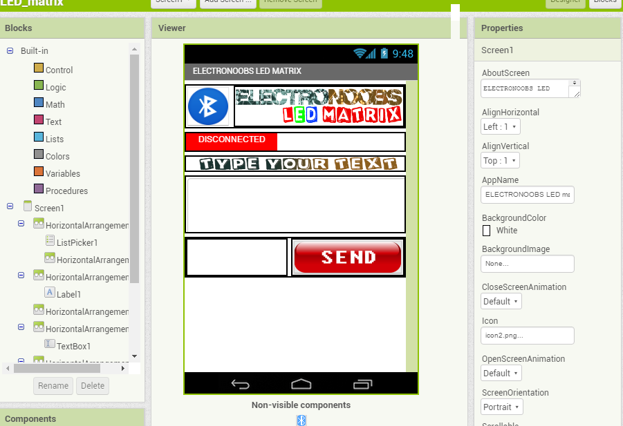
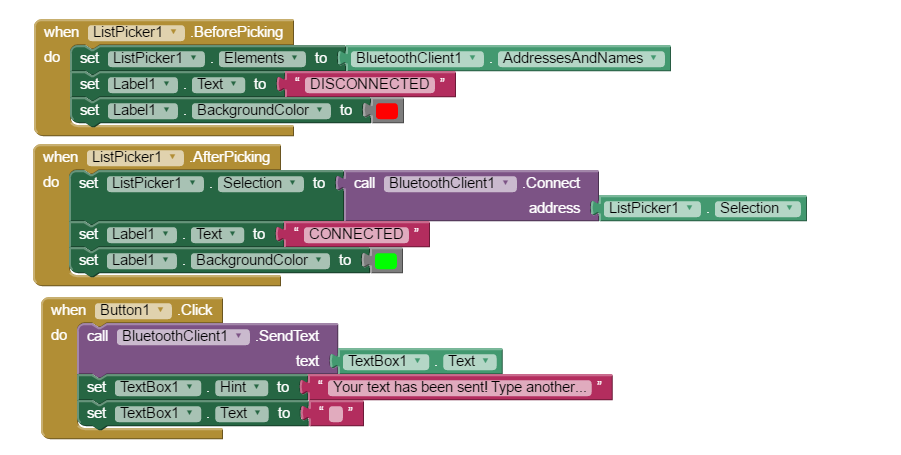
The App
Ok, so to send text to our huge LED matrix we have to establish a bluetooth connection between our Android smartphone and the arduino. For that I've created the next App using App inventor. If you want to learn how to create your own Arduino App just watch my video.
The next app has one button for bluetooth connectiom, one text box and a button to send the text.
You can download this app from the link below. Copy the apk file to your smartphone using a USB connection or just download the App directly to your phone.
Before we open the App we have to syncronise the bluetooth module. For that go to bluetooth setings on your smartphone and search for devices. When found, select the hc06 module and use the 0000 or 1234 passwrod to syncronise. We're done. Now open the app. Click the bluetooth icon and select the hc-06 module. Type your text and send.