
 About me
  History
  Let's learn
  Contact us
  Arduino tutorials
 Circuits tutorials
  Robotics tutorials
 Q&A
Q&A Blog
Blog  Arduino
  Circuits
 Robotics
  Modules
  Gadgets
  Printers
  Materials
  3D objects
  3D edit
  Donate
  Reviews
  Advertising


Arduino ANDROID App RGB LED strip control
The App
You want to dowload my App?
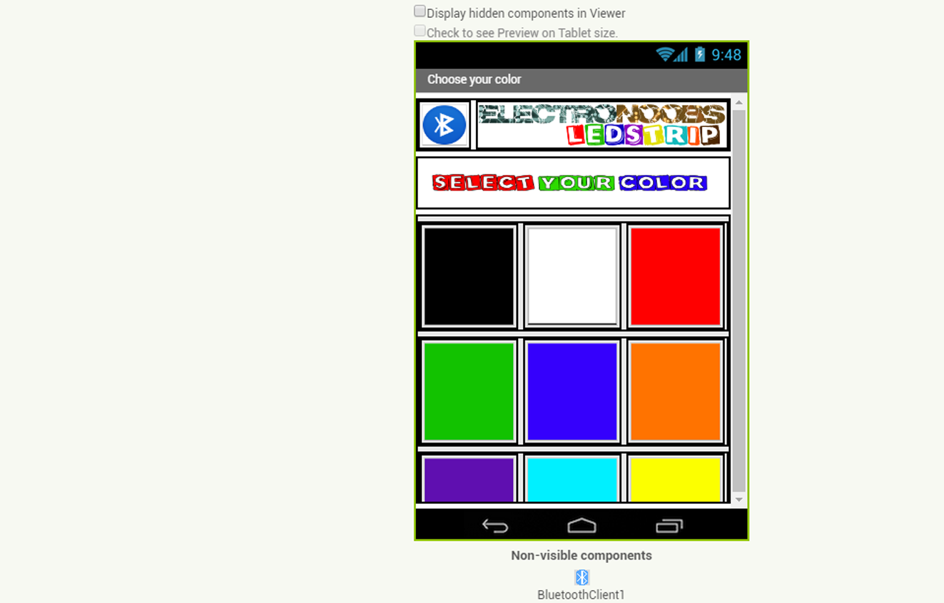
I've designed my App in App inventor. If you want to see step by step how to create one, just folow this other tutorial of mine. This will be the main interface of the App with a button for each color. The app also has the bluetooth button. When pushed it will open the bluetooth devices list. Select the HC06 device in that lis in order to connect.
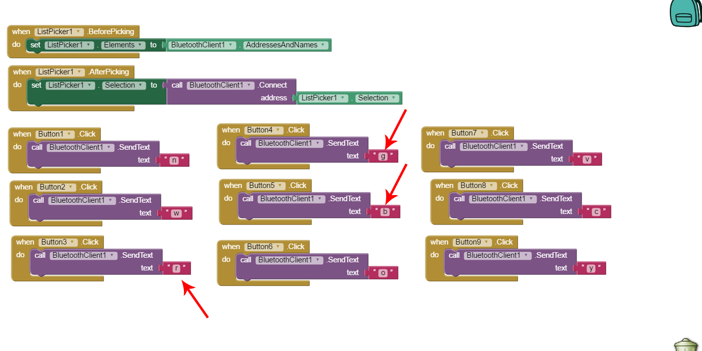
Now if we take a look in the blocks section we can see that the App will send a different character for each color button. Like for example "r" for red, "b" for blue, "g" for green and so on... The arduino will receive those values and it will have to take the decision on what signals to activate.
Download the App from the next link. Copy it on to your smartphone device using a USB connection or directly download the app using your android phone.
Before you install it you should allow unknown origin aplication to be installed. For that open your smartphone, go to settings, security, and check the "allow unknown origin aplications". Now open the folder where the App is and install it. Before we start the App we have to syncronise the devide. Open the bluetooth settings on your smartphone. Search for devices and select the HX06 when found. The password should be 1234 or 0000. Now we are syncronised. Open the App, click the bluetooth icon and select the HC06 device from taht list. Now just select your color and observe the magic. Oh, yeah, we have to programe the Arduino!. Take a look at the next code.
The Code NPN
There will be a different code for thr NPN schematic and other for the PNP. Just download the sketch or copy it from below. There is no extra library to install so the code should work for any Arduino IDE.
/* RGB LED strip with arduino and Android App bluetooth connection
 *  http://www.electronoobs.com
 *
ARDUINO       RGB
  3          RED
  5          GREEN
  9          BLUE

Bluetooth HC-06 module and Arduino
ARDUINO    Bluetooth HC-06
 0 (RX)       TX
 1 (TX)       RX
 5V           VCC
 GND          GND
 */
///////////////////////////////pre upload ERROR////////////////////////////////////
//#error delete this line after you make sure that the Tx and Rx pin are disconnected
//Tx and Rx pins of the HC06 module should not be connected while we upload the
//"Sketch" to the arduino. The code won't be upload if the pins are connected
///////////////////////////////////////////////////////////////////////////////////
int color=0;

//define the RGB pind
int red = 3;
int green = 5;
int blue = 9;

char received;

void setup()  {
  Serial.begin(9600);     //Start the serial comunication for the bluetooth module
  pinMode(red, OUTPUT);   //Red color pwm pin defined as output
  pinMode(green, OUTPUT); //Green color pwm pin defined as output
  pinMode(blue, OUTPUT);  //Blue color pwm pin defined as output

  //Give first value of the PWM 0, we start with the RGB LEDs off
  analogWrite(red,0);
  analogWrite(green,0);
  analogWrite(blue,0);

 }

void loop()  {

  if(Serial.available()>0){
    // read the bluetoot data and store it
    color = Serial.read();
    char Rec = char(color);
    if (Rec != '0')
    {
    Serial.println(Rec); //This is to visualise the received character on the serial monitor
    }
  }

  //LEDs off
  if (color == 'n')
  {
    analogWrite(red,0);
    analogWrite(green,0);
    analogWrite(blue,0);
  }
  //White
  if (color == 'w')
  {
    analogWrite(red,255);
    analogWrite(green,255);
    analogWrite(blue,255);
  }
  //Red
  if (color == 'r')
  {
    analogWrite(red,255);
    analogWrite(green,0);
    analogWrite(blue,0);
  }
  //Green
  if (color == 'g')
  {
    analogWrite(red,0);
    analogWrite(green,255);
    analogWrite(blue,0);
  }
  //Blue
  if (color == 'b')
  {
    analogWrite(red,0);
    analogWrite(green,0);
    analogWrite(blue,255);
  }
  //Orange
  if (color == 'o')
  {
    analogWrite(red,255);
    analogWrite(green,153);
    analogWrite(blue,0);
  }
  //Violet
  if (color == 'v')
  {
    analogWrite(red,102);
    analogWrite(green,0);
    analogWrite(blue,153);
  }
  //Cyan
  if (color == 'c')
  {
    analogWrite(red,0);
    analogWrite(green,255);
    analogWrite(blue,255);
  }
  //Yellow
  if (color == 'y')
  {
    analogWrite(red,255);
    analogWrite(green,204);
    analogWrite(blue,0);
  }
}