In this tutorial we will see how to make a Magic 8 ball with the Arduino. This is based on the real magic ball which is based on liquid and floating principle with a plastic dice with 20 answers inside. Once you shake the ball, a random side of the dice will get on top of the black liquid and a random answer will be shown.
In our case, we will do that digitally. The project will use a gyro module to detect when the ball is upside down. Then it will give a random answer to the OLED display. At the same time using a DFplayer it will play sounds with the answers. It also has a battery inside that we could charge and the case is made out of 3D printed parts.
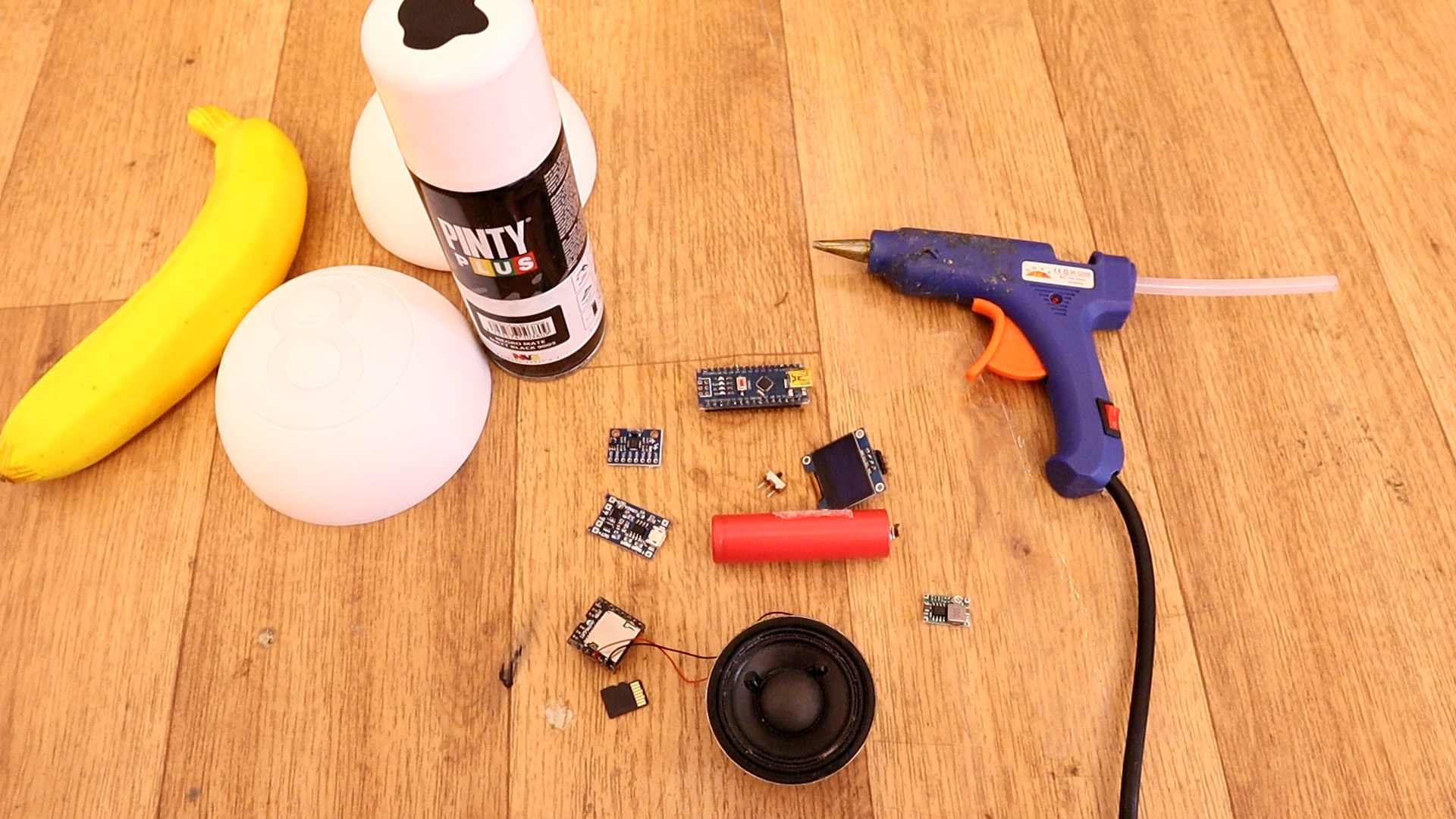
This project is easy and the part list is quite straightforward. The Arduino will control everything. To detect the angle of rotation and by that know when the ball is upside down we will use the MPU6050 gyro module. To print the text we need an OLED display and to play sounds we will use the DFplayer with the SD card and a small speaker. We need a 18650 battery and a charging module and to get 5V we need a small boost converter. We will also need glue and small wires.
See the schematic below. It is very simple. All we have to do is to connect the i2c pins (SDA and SCL) to the A4 adn A5 pins of the arduino. For 5V supply, first connect the charging module to the 3.7V battery. Then the output of the module, connect the positive side to the sliding switch and the negative output to GND. GND is the same for all parts. From the switch, connect it to the boost converter adn before you connect it to anything else, make sure you set it at 5V. You could glue the boost converter potentiometer so it will stay at 5V. Connect the Rx and Rx pins from the Arduino to some 1K resistors and from there to the Tx and Rx pins of the DF player.
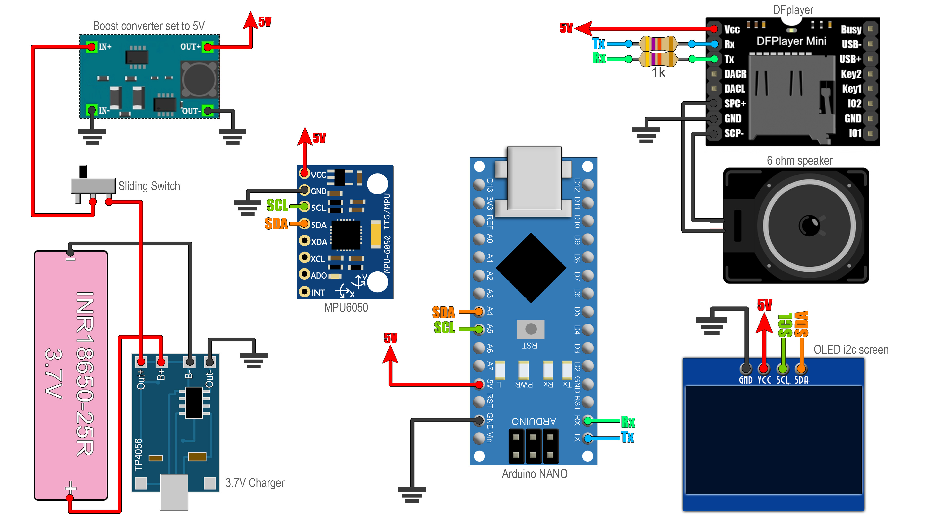
As you can see, for the DFplayer, we connect Tx to Rx and Rx to Tx. Connect the speaker at the DFplayer spk outputs and that's it. The IMU and the OLED display are using the same i2c pins because they have different slave address. All is there to do is to mount this inside the 3D case and upload the code.
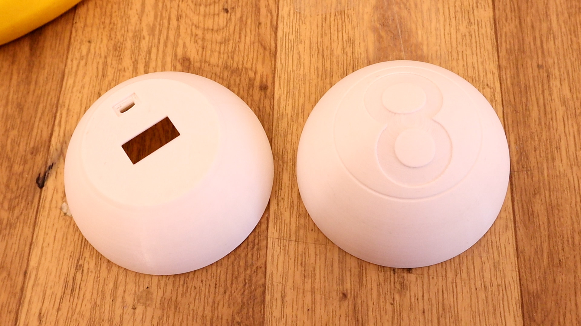
First we need the 3D case. For that go to the STL download page and get the files. Print them using 0.4mm nozzle, PLA material, 0.3mm layer height, 2 perimeters and 20% infill. You don't need to use support for the parts of this case. Now is time to glue the circuit inside the case. But I recommend you to test the circuit on a breadboard first and then glue it inside the case. Get the code from next part.
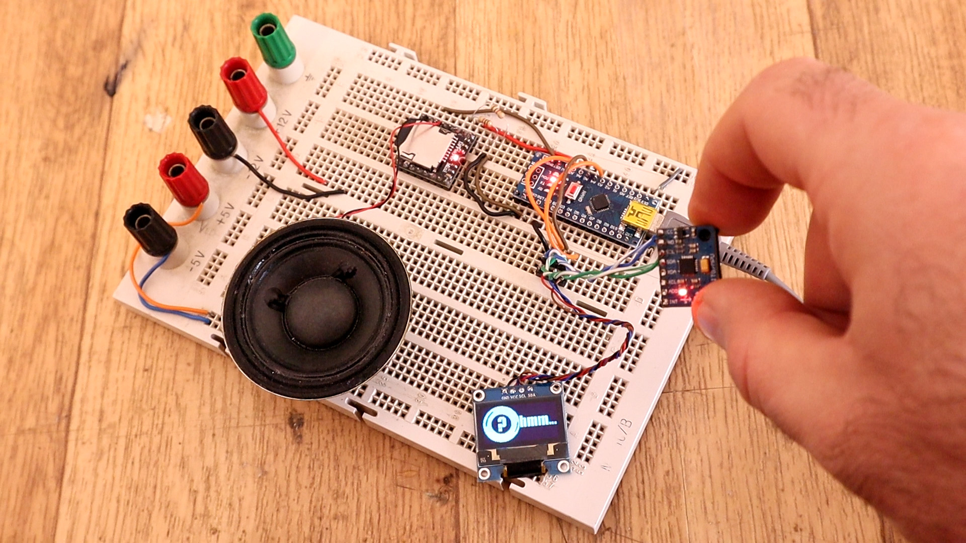
I've connected everything on the breadboard and uplaoded the code from next part. Also, you will need the mp3 files from below. Download those and copy the entire mp3 folder to an empty SD micro card. It has to be the entire mp3 folder with taht name, not only the files. Insert the SD cart into the DFplayer and test the code. Rotate the IMU module and watch the screen and listen the sounds.
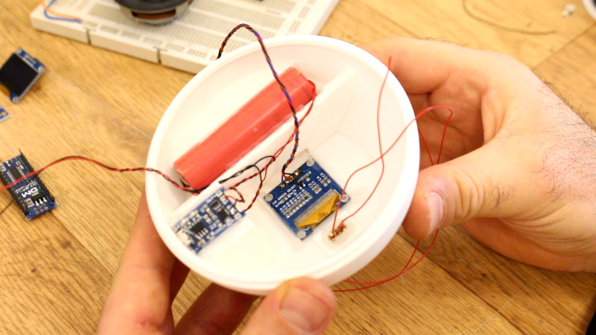
Ok, the first step of mounting the ball is to glue the OLED display on the bottom hole as you can see below. Then connect the Bat+ and Bat- pins to the battery and from the module output to the sliding switch. Glue the switch below the OLED display and make sure it won't stick out of the case too much so the ball could sit flat on the table.
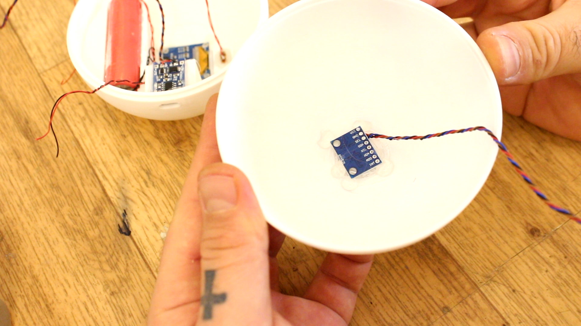
The next step is to solder wires to the IMU module for GND, power, data and clock. Make sure the wires are a bit long because this component will go on the other side of the ball. Then, glue the IMU module on the top part of the ball, paralel with the 8 shape on top and with the chip facing the exterior of the ball. Is important to be paralel with the 8 shape on top because we will only detect the X axis rotation.
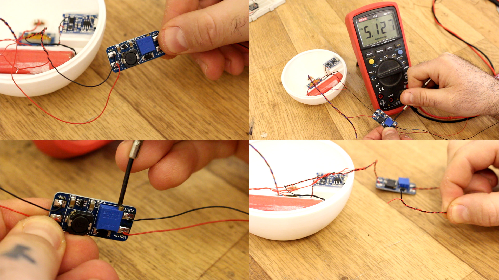
Next step is important. Connect the battery output to the boost converter. Then rotate the potentiometer till you get 5V. Then glue the potentiometer so it will stay at that voltage and we won't burn the Arduino. Now tje output from the boost converter will be our main 5V supply and we can connect this to the rest of the modules: Arduino, DFplayer and the IMU module.