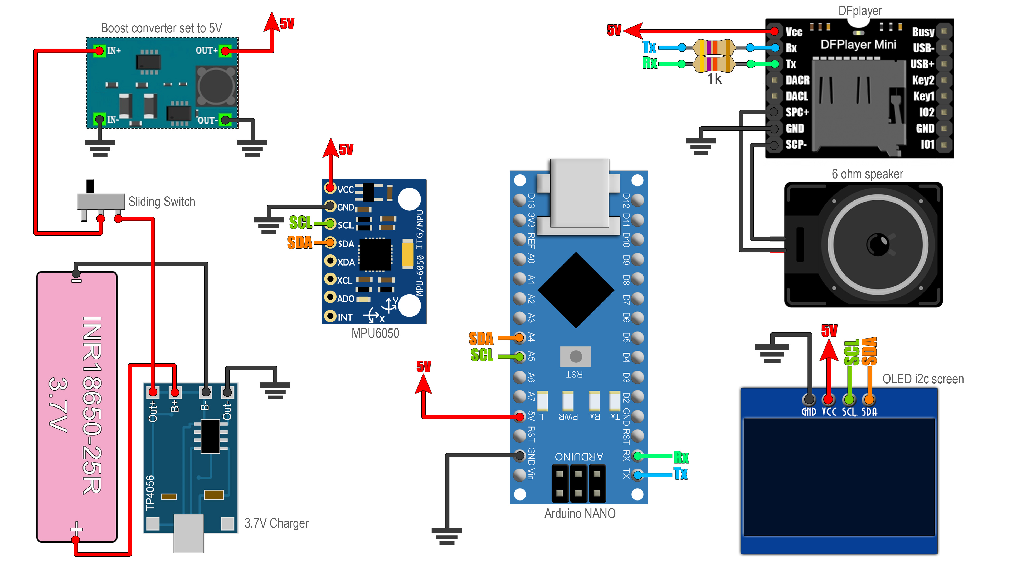
See the schematic below. It is very simple. All we have to do is to connect the i2c pins (SDA and SCL) to the A4 adn A5 pins of the arduino. For 5V supply, first connect the charging module to the 3.7V battery. Then the output of the module, connect the positive side to the sliding switch and the negative output to GND. GND is the same for all parts. From the switch, connect it to the boost converter adn before you connect it to anything else, make sure you set it at 5V. You could glue the boost converter potentiometer so it will stay at 5V. Connect the Rx and Rx pins from the Arduino to some 1K resistors and from there to the Tx and Rx pins of the DF player.