In this tutorial we will make a homemade lidar. Is not as good as commercial lidar sensor, but it would be good enough for some small robot to avoid obstacles. I will show you what is a lidar sensor, how they work and how I’ve made a homemade one based on Arduino and an infrared distance sensor. I’ve designed and 3D printed a case in such a way that it could spin 360 degrees without stopping. For better support it also has a big bearing inside. The spin is controlled by a step motor and the lidar has a basic output, with values of angle and distance. We could use these values to create an obstacles map around our robot for examples. I will also show you how to get better results in case that you need higher precision.
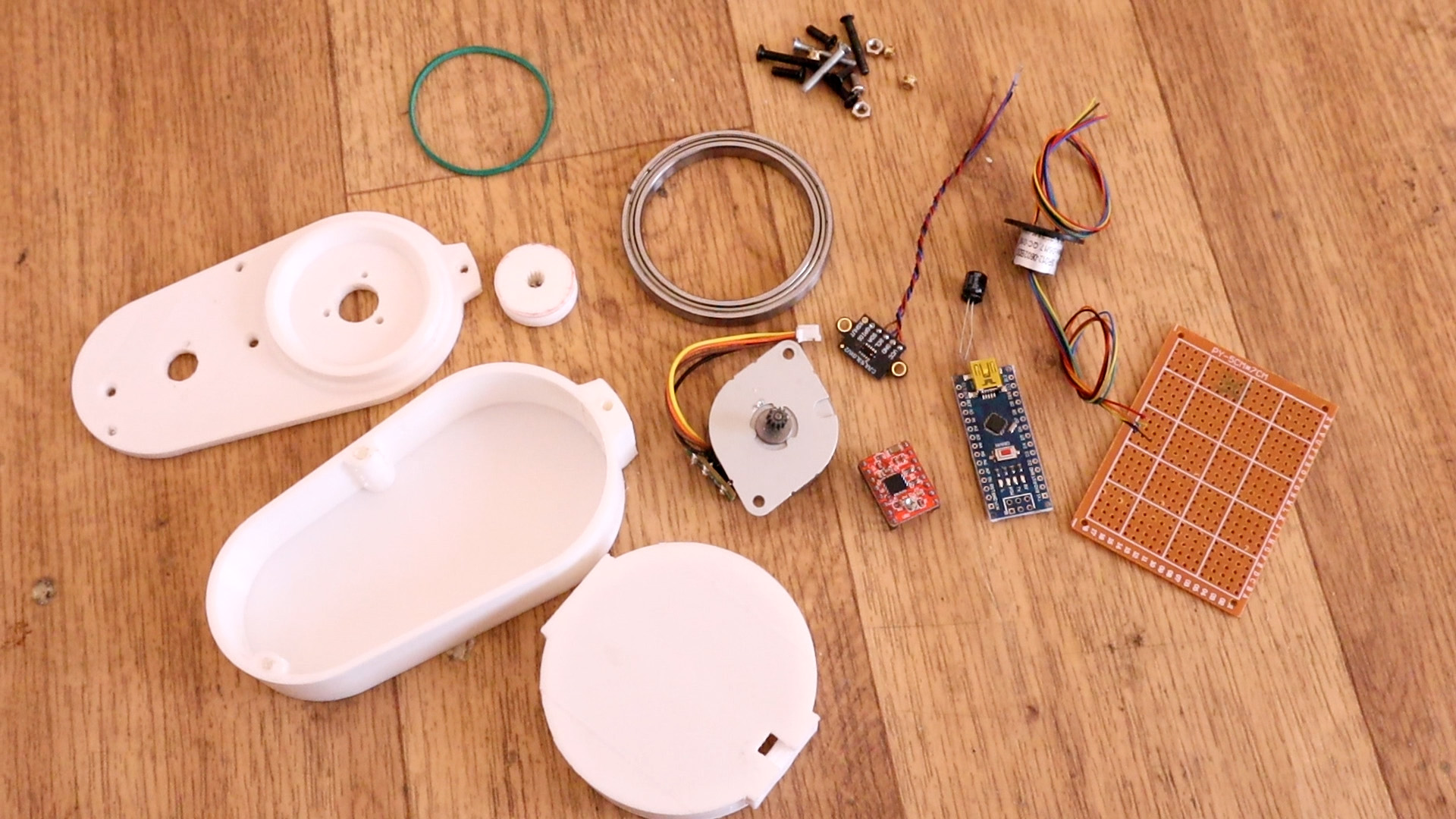
This is what we need for this project. Firs, download the 3D files from below and print them with PLA. Then go and buy the motor, the distance IR sensor and the resto of the small parts such as the drivers, the Arduino and so on. You will also need an elastic rubber band, solder and a soldering iron.
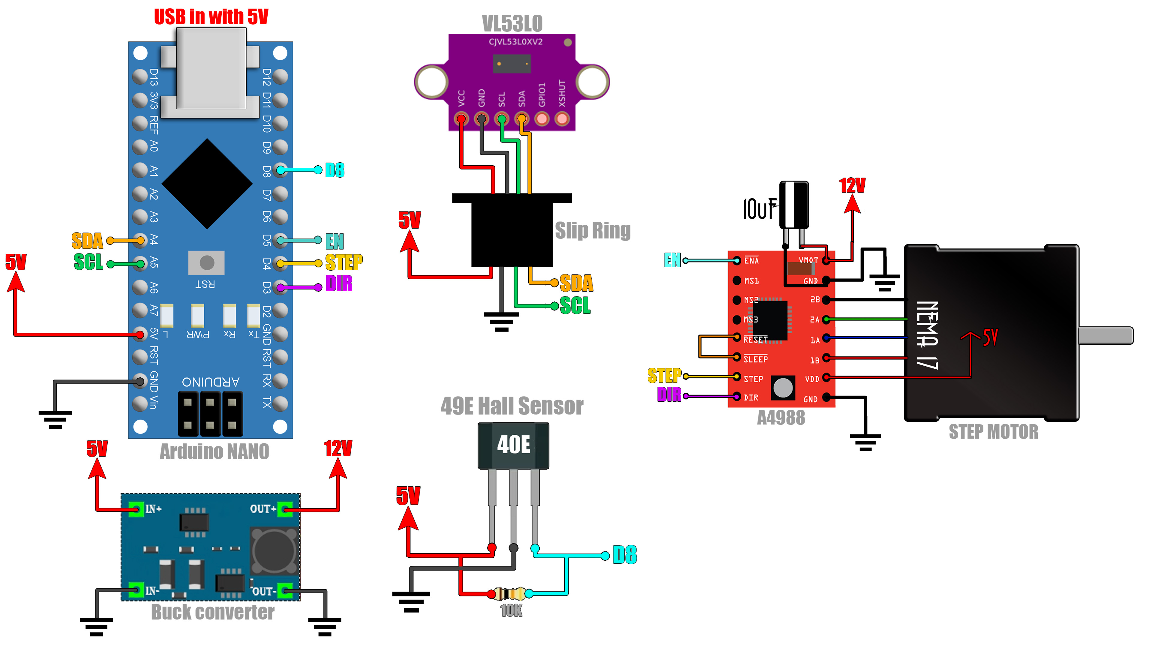
Schematic is simple. Connect the i2c pins from the Arduino to the Slip ring. From the SLip Ring to the VL53L0 distance sensor. Then connect 5V and the D8 pin to the Hall sensor. Connect enable, step and direction to the step motor driver and the motor to the driver. Now connect 5V to the boost converter and set the output to 12V and connect that to the pwoer input of the step motor driver. That's it. As a supply I'm using the USB cable connected to the Arduino.
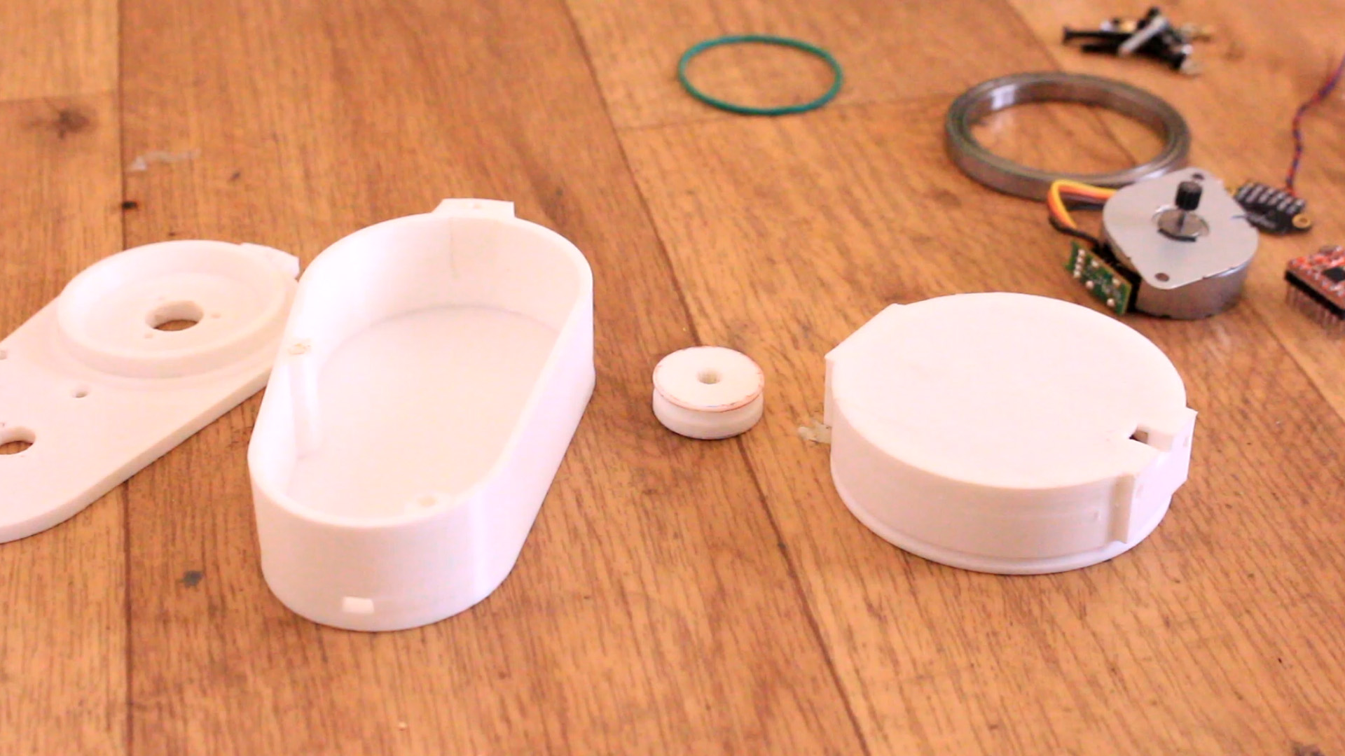
Downlaod the 3D stl files from above from the part list. Print the case with 2 perimeters, 0.3mm layer height, PLA material and 20% infill. Now we have the case, the rotating disc and the pully. We can mount everything inside so let's see.
Ok, now take the slip ring and place it on the top part of the case. Make sure that the rotating part of the ring is on the above side of the case so it will spin at the same time as the disc. Now, add the step motor using 2 3M screws and nuts. Not the top part of the case is ready and we have the wires from the slip ring on the inner side of the case.
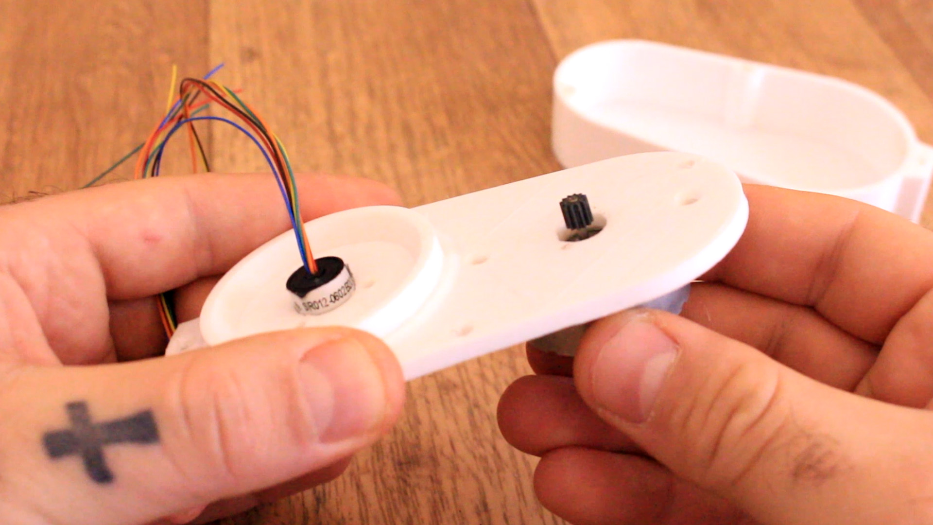
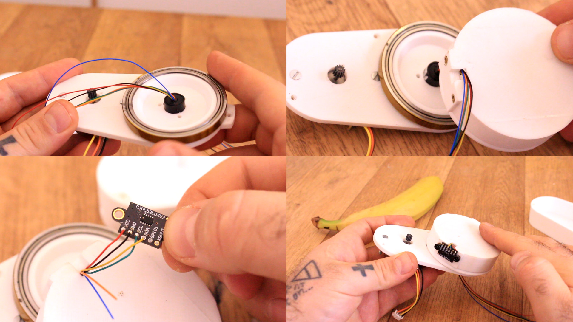
Ok, now we can add the big bearing on the top part of the case. Then, pass the wires from the slip ring though the hole of the rotating disc. Once you do that solder 4 wires to the distance sensor for 5V, GND, data and clock of the i2c communication. Now, screw in place the sensor using those metal inserts you can find in the part list and 2 M3 screws. Now you can close the rotating disc over the bearing.
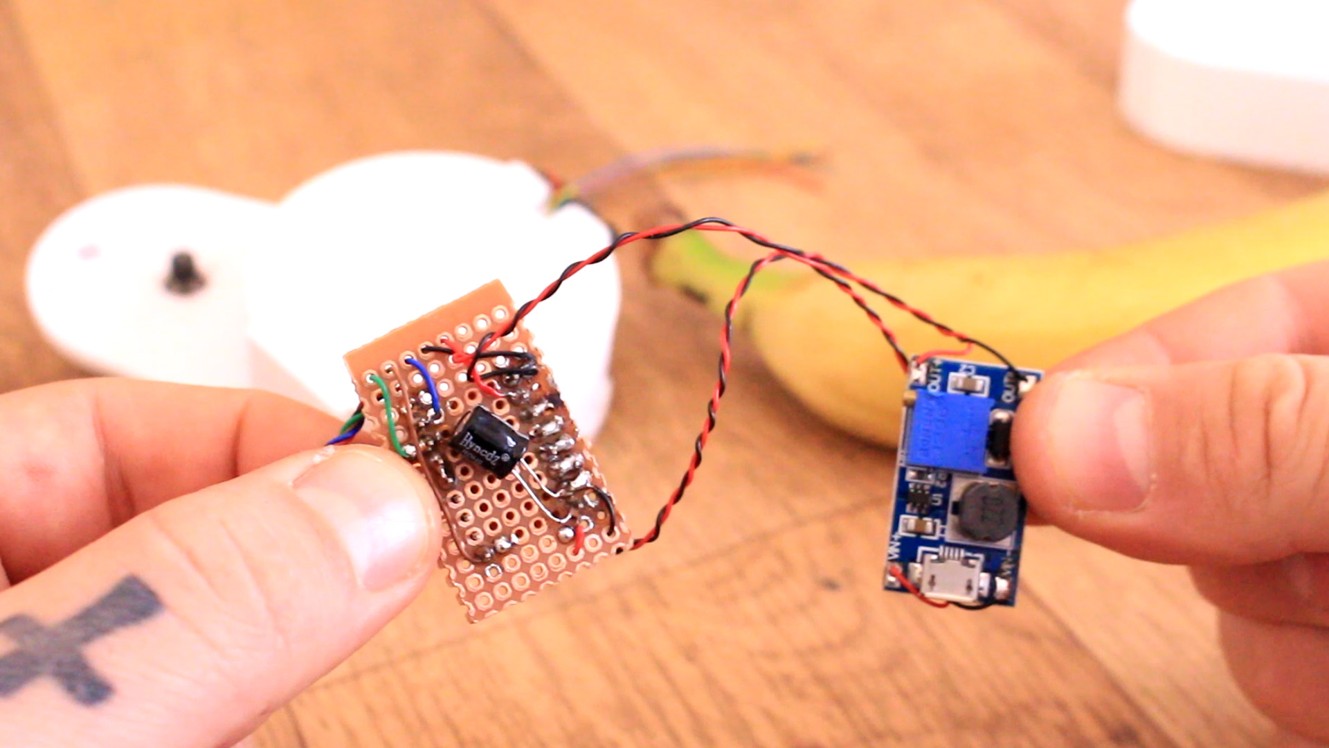
Ok, now this is an important step. Get the boost converter and solder wires for 5V. Then supply the converter and set it to 12V and then you can solder wires from the output to the step motor driver. Now the driver is supplied with 12V. We can solder the rest of the components.
Finally, add the hall sensor as in the schematic with a 10K resistor and connect it to D8 pin of the Arduino. Glue taht in place on the side of the rotating disc and on the disc solder the magnet. In this way we can detect the rotation of the lidar. Solder the magnet in the oposite side of the distance sensor so we have 180 degrees diference. Now, solder everything together and we can close the case. Glue the Arduino with the USB connector in front of the hole of the case. That's it. Upload the code below.