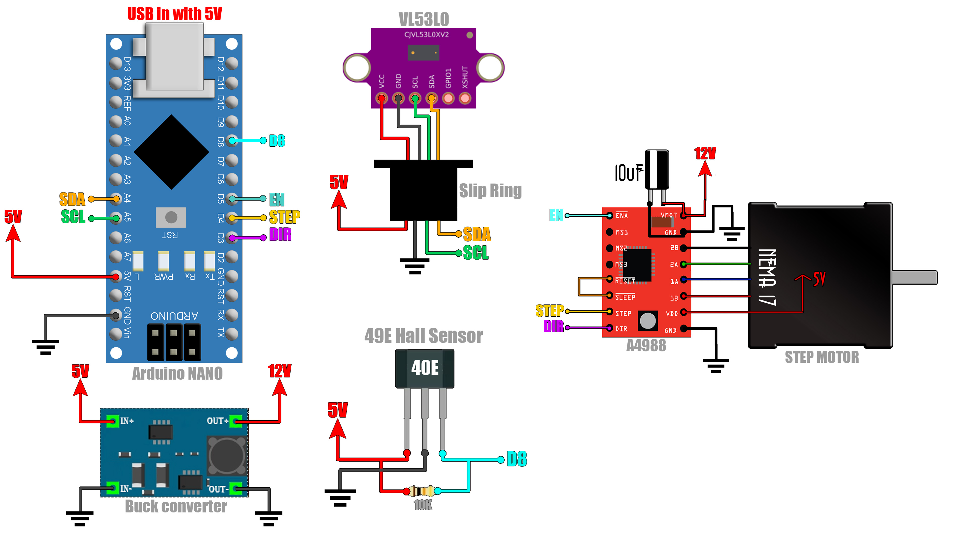
Schematic is simple. Connect the i2c pins from the Arduino to the Slip ring. From the SLip Ring to the VL53L0 distance sensor. Then connect 5V and the D8 pin to the Hall sensor. Connect enable, step and direction to the step motor driver and the motor to the driver. Now connect 5V to the boost converter and set the output to 12V and connect that to the pwoer input of the step motor driver. That's it. As a supply I'm using the USB cable connected to the Arduino.