
We want a radio communication between two Arduinos. These two very cheap modules will be useful for a small project wghere we need short-range.
by: ELECTRONOOBS on 2026-05-25
All the prices are low due to China purchase. It's up to you wait or not.
1. Two Arduino pro mini (small size) (2€-3€) LINK eBay
2. One radio receiver 433 MHz (1€-2€) LINK eBay
3. One radio transmitter 433 MHz(1€-2€) LINK eBay
4. Serial TTL/FTDI FT232RL module (If you use a pro mini) (2€-3€) LINK eBay
5. Wires, conectors, solder, soldering iron... (0€)
Into!
The maximum range of operation of these modules won't exceed 20m. They are very easy to use and connect. You only need a single power and data connection. The disadvantage is that we can only send one bit at a time so the speed is not very fast and the data packege is very small. But to create such a remote control for your robot (see gallery) would be perfect if we only use high and low states of your buttons.
We will also see how to increase the operating range of the modules by adding a small antenna.
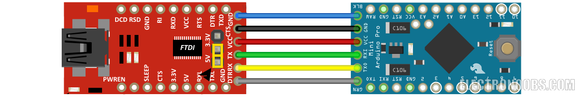
First of all we need to power the Arduino FTDI connecting the module 5 volts to Vcc arduino. We also connect the GND to GND of the microcontroller. We have powered the Arduino. If using an Arduino pro mini here you have the connection with the FTDI module to program the microcontroller:
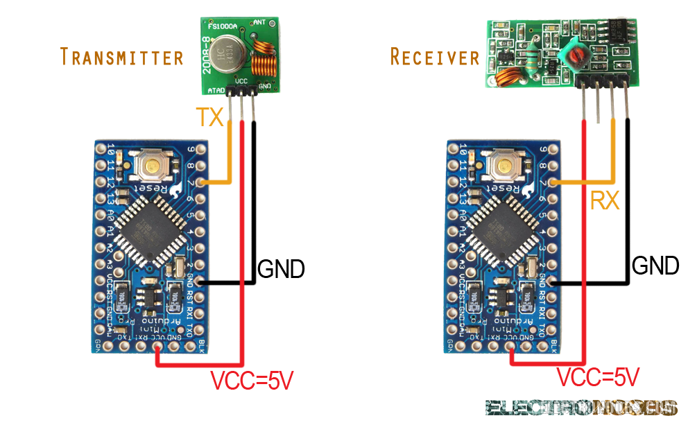
Once we programmed we connect to the RAW pin a voltage between 6 and 12 volt (battery, USB, etc.) The connection is simple. We power each module with a voltage of 5 volts Vcc directly from arduino. Connect the ground to ground and data to any digital pin of the arduino. I've choose pin D7 this time. In the receptor case, any of the two middle pins serve. The two are the same RX pin. For this project we need the VirtualWire library before compiling and programming the microcontroller.
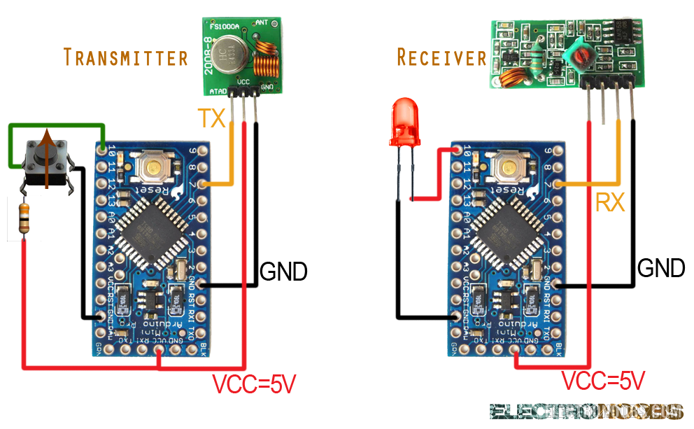
To install it we just go to Program -> inport library and we open the .zip file that we've just downloaded. In order to test our connection we will use one push button and one LED. We connect the push button to ground and the other pin of the button thrw a pullup resistor to Vcc. The same pin of the push button that was conected to ground will go to one of the digital pins of the arduino. In this case will be pin D10. In this way if we don't push the button we will have a low digital input and every thime that we press it we will have a high input.
//Transmitter code (ProMini)

#include <VirtualWire.h>//We inport necessary libraries
#include <Wire.h>

int boton=10;//We create the button input using pin 10

void setup() {
pinMode(boton,INPUT);//The D10 pin as input
vw_setup(4000);//comunication speed, it can be 2000, 4000 and up to 8000
vw_set_tx_pin(7);//Pin 7 is the TX pin
}

void loop() {

//Low input -> we send a "0"
if (digitalRead(boton)==LOW)
{
char msg[1] = {'0'};
vw_send((uint8_t *)msg, 1);
vw_wait_tx();
}

//Hign input -> we send a "1"
if (digitalRead(boton)==HIGH)
{
char msg[1] = {'1'};
vw_send((uint8_t *)msg, 1);
vw_wait_tx();
}
}//Receiver code (ProMini)
#include <VirtualWire.h>//Inport necessary libraries
#include <Wire.h>
int LED=10;//We create the led output using D10 pin
void setup() {
pinMode(LED,OUTPUT);//Define the 10 pin as output
vw_setup(4000);//comunication speed, it can be 2000, 4000 and up to 8000
vw_set_tx_pin(7);//define the 7 pin as RX pin
}
void loop() {
uint8_t buflen = VW_MAX_MESSAGE_LEN;
uint8_t buf[buflen];
if(vw_get_message(buf, &buflen))
{
for(int i = 0;i < buflen;i++)
{
if(buf[i] == '0')//If a "0" is received we turn off the led
{
digitalWrite(LED,LOW);
}
else if(buf[i] == '1')//If a "1" is received we turn on the led
{
digitalWrite(LED,HIGH);
}
}
}
}Comments


Leave a comment
Please login in order to comment.