
 About me
  History
  Let's learn
  Contact us
  Arduino tutorials
 Circuits tutorials
  Robotics tutorials
 Q&A
Q&A Blog
Blog  Arduino
  Circuits
 Robotics
  Modules
  Gadgets
  Printers
  Materials
  3D objects
  3D edit
  Donate
  Reviews
  Advertising


RC receiver with NRF24 module
1.
2.
3.
4.
5.
6.
Intro!
We receive our signal from the transmitter created in the other tutorial. We receive the signal, map the values in the desired range and create a PPM or PWM output of our received channels in order to connect them to our machine (drone, robot, etc ...) application. PPM is much useful when making a communication between two Arduinos because you only neeed one digital pin output and input and using that pin you can comunicate up to 8 channels of PPM. Since my aplication will use arduino as well I will use PPM output. There will be the code fot PPM and PWM as well.
Connections!
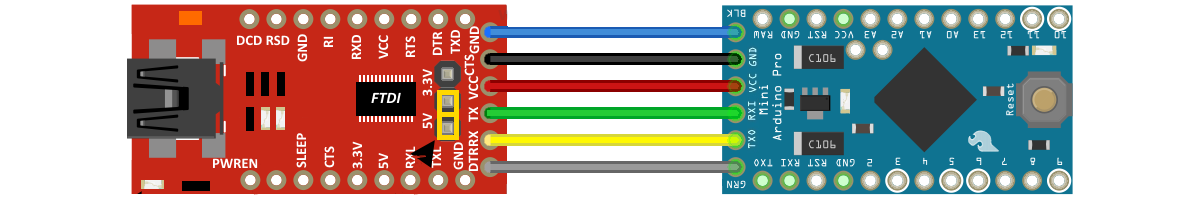
First of all if using an arduino pro mini we need to power the Arduino FTDI connecting the module Vcc 5 volts to the Vcc of the arduino. Also we connect the GND to GND of the microcontroller.
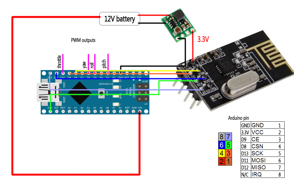
Using arduino nano just connect the USB to it and upload the code. Connect the NRF24 module to the external 3.3V regulator because this module needs a lot of current. Once we programmed our microcontroller we connect the battery directly to RAW with a voltage between 6 and 12 volts.
The pin connection of the NRF24 module appears on the schematic. Be carefoul because we've used the pin 8 in stead of pin 10 for the CSN connection.
We can see that we have four analog outputs which are the 4 values received from the transmitter. When connecting this pins to our (for example) flight controller of our drone, they need to share ground as well, otherwise they won't work.
You can download the
To install it we just go to Program -> inport library and we open the .zip file that we've just downloaded.
PPM receiver code!
/*
4 cnannels rf receiver (PPM output)
*/
#include <
#include <nRF24L01.h>
#include <RF24.h>
////////////////////// CONFIGURATION del PPM//////////////////////////
#define channel_number 4 //we will have 4 channels
#define sigPin 2 //The PPM output will be pin D2
#define PPM_FrLen 27000 //frames per seccond of the PPM (1ms = 1000µs)
#define PPM_PulseLen 400 //pulse width config
//////////////////////////////////////////////////////////////////
//EThis part of code should be the same as the transmitter
RF24 radio(9, 8); //pin 8 is CSN!
//Up to 32 channels
struct MyData {
};
MyData data;
{
//We give the start value of each byte
data.throttle = 0;
data.yaw = 127;
data.pitch = 127;
data.roll = 127;
setPPMValuesFromData();//we call this function that will map the values
}
{
ppm[0] =
ppm[1] =
ppm[2] =
ppm[3] =
//This is an example used in a drone project. My drone use microseconds
//signals with a range between 1000 and 2000. That is why
//I've maped my values in this way. You should change the values as you desire
//afor your application.
}
/**************************************************/
cli();
TCCR1A = 0; // We set to 0 the TCCR1 register
TCCR1B = 0;
OCR1A = 100;
TCCR1B |= (1 << WGM12); // We start CTC mode
TCCR1B |= (1 << CS11); // 8 prescale: 0,5 microseconds at 16mhz
TIMSK1 |= (1 << OCIE1A); // Interrupt enable
sei();
}
{
resetData();
setupPPM();
radio.
radio.setAutoAck(
radio.setDataRate(RF24_250KBPS);
radio.openReadingPipe(1,pipeIn);
radio.startListening();
}
/**************************************************/
{
radio.
lastRecvTime =
}
}
/**************************************************/
{
recvData();
// Ha perdido la señal?
resetData();
}
setPPMValuesFromData();
}
/**************************************************/
#error Make sure that your clockMultiplier is the correct one (below). Delete this line after that
#define clockMultiplier 1 //set this to 2 if you're using a 16MHz arduino, leave it to 1 for a 8MHz arduino
ISR(TIMER1_COMPA_vect){
TCNT1 = 0;
//end pulse
PORTD = PORTD & ~B00000100; // turn off D2
OCR1A = PPM_PulseLen * clockMultiplier;
state =
}
//start pulse
PORTD = PORTD | B00000100; // turn on D2
state =
cur_chan_numb = 0;
calc_rest += PPM_PulseLen;
OCR1A = (PPM_FrLen - calc_rest) * clockMultiplier;
calc_rest = 0;
}
OCR1A = (ppm[cur_chan_numb] - PPM_PulseLen) * clockMultiplier;
calc_rest += ppm[cur_chan_numb];
cur_chan_numb++;
}
}
}
PWM receiver code!
/*
4 channels receiver example (PWM output)
*/
#include <
#include <nRF24L01.h>
#include <RF24.h>
RF24 radio(9, 8); //Remember, here we changed the CSN pin from 10 to 8
//We could use up to 32 channels
struct MyData {
};
MyData data;
{
//We define the inicial value of each data input
//3 potenciometers will be in the middle position so 127 is the middle from 254
data.throttle = 0;
data.yaw = 127;
data.pitch = 127;
data.roll = 127;
}
/**************************************************/
{
//We define the H bridge output pins
resetData();
radio.
radio.setAutoAck(
radio.setDataRate(RF24_250KBPS);
radio.openReadingPipe(1,pipeIn);
//we start the radio comunication
radio.startListening();
}
/**************************************************/
{
radio.
lastRecvTime =
}
}
/**************************************************/
{
recvData();
unsigned long
//Here we check if we've lost signal and if we did we reset the values
// Signal lost?
resetData();
}
//we make an analogWrite using the received values
}
/**************************************************/