
 About me
  History
  Let's learn
  Contact us
  Arduino tutorials
 Circuits tutorials
  Robotics tutorials
 Q&A
Q&A Blog
Blog  Arduino
  Circuits
 Robotics
  Modules
  Gadgets
  Printers
  Materials
  3D objects
  3D edit
  Donate
  Reviews
  Advertising


Plasma arc lighter
Flyback transformer
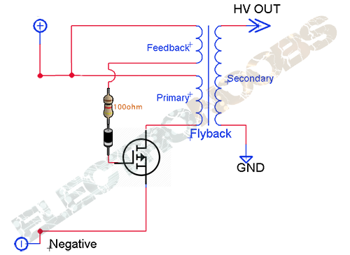
Our circuit
When the switching transistor is turn on in a fly-back converter, the primary winding of the transformer is energized as we talk about earlier (inductor), and no energy is transferred to the secondary windings. When the transistor is turned off the field collapses and the energy is transferred to the secondary windings. This differs from a forward converter topology, where energy is transferred to the secondary windings when the switching transistor is turned on. You can easily tell the difference between these two topologies.
So how this circuit works? When power is applied to the positive and negative terminal, current begins to flow through the feedback coil to the base of the transistor. This turns on the transistor, and current flows through the primary coil. As this happens, a voltage is induced in the secondary creating our high voltage spark because of the stored energy in the coil before the transistor switch. At the same time, another smaller voltage is also induced on the feedback winding, opposite in polarity of the base voltage causing the transistor to turn off. As the magnetic field collapses, again high voltage is induced in the secondary. Now there is no more feedback current in the feedback coil, and once again current flows through the primary because the transistor is switched on once again, and the cycle repeats at its own natural frequency over and over again. Because of this, the circuit is self-oscillating and settles at its optimal frequency depending on the loading. So this should create our high frequency high voltage. This kind of voltage should create our plasma arc.
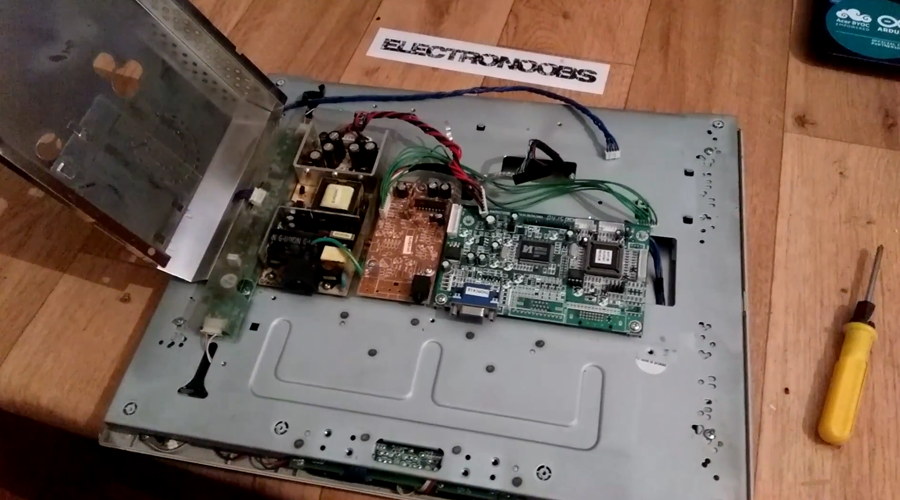
For that we need a flyback high voltage transformer. We have two options. It all depends on the material that we have. We could find a high voltage transformer usually inside any LCD screen. I have this old broken LCD monitor laying around my workshop. I will take the high transformer out. If you don’t have an LCD monitor we will se how to build a high voltage transformer later. But first let’s open the LCD.
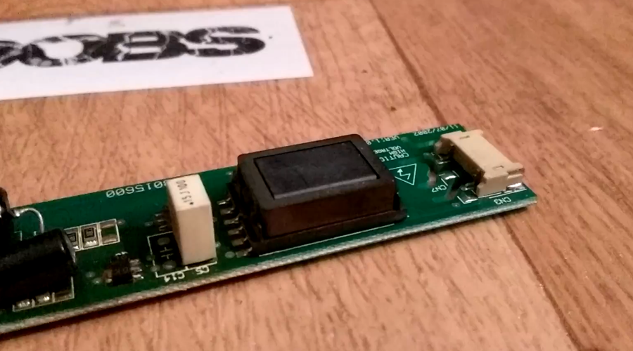
Flyback transformer out of the LCD
It is quite easy to identify the transformer. The LCD screen has some cold neon tubes that light up the entire screen. Those neon tubes work with high voltages. So identify the circuit with high voltage labels and wires that go to the top and botton of the screen. There is where usually the neon tubes are. Here it is.
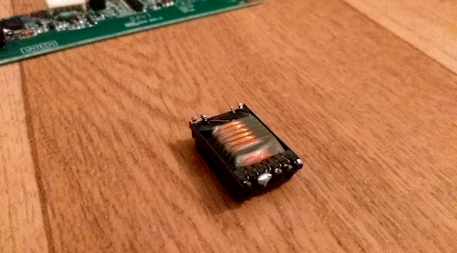
To take it out I first fill the pads with solder. Now I heat the two pins at the same time and take it apart. I do the same for the other side. So this is the High voltage transformer. We can see that the secondary coil is separated in a few layers. That is to prevent arcs discharges inside of the transformer. We don’t want that. At the bottom we have our primary and flyback coils. This transformer usually gives us a few hundred volts or maybe more. If we were to use it in our project we should unwind the primary coil and wind a new one with less windings. Around 4 to 5 windings for the primary coil. The secondary should stay the same.
Another option, if we don’t have the LCD screen, is to build our own high voltage transformer. I’ve use this small transformer that I’ve took out from an old computer power supply. You could find this small transformers in all kind of power supplies, mobile transformers, laptop chargers and so on. All we need is to make sure that the ferrite core is not broken.
Next page: