
Double rail means that it could give both positive and negative values, for example +12V and -12V. Usually my projects work with a battery or maybe some kind of DC adapter. All those supplies give a steady positive DC voltage but sometimes we also need negative values and these are the topics we will see in todays post. And if you wonder, we must use this kind of dual rail power supply for audio amplifiers, sometimes with operational amplifiers if you want negative and positive values, some ADCs and DACs also need dual rail supply and even LCDs need a dual rail supply to switch the pixels on and off. If you remember, a few years back I made my own ultrasonic sensor. To be able to vibrate the ultrasonic speaker I needed plus minus 20 volts and that’s another example where I’ve used a dual rail supply. So as you can see, is a quite important topic. So what options do we have to get positive and negative supply? We will check a few circuits and examples from a basic one to a bit more complicated and understand how they work. So guys let’s get started.
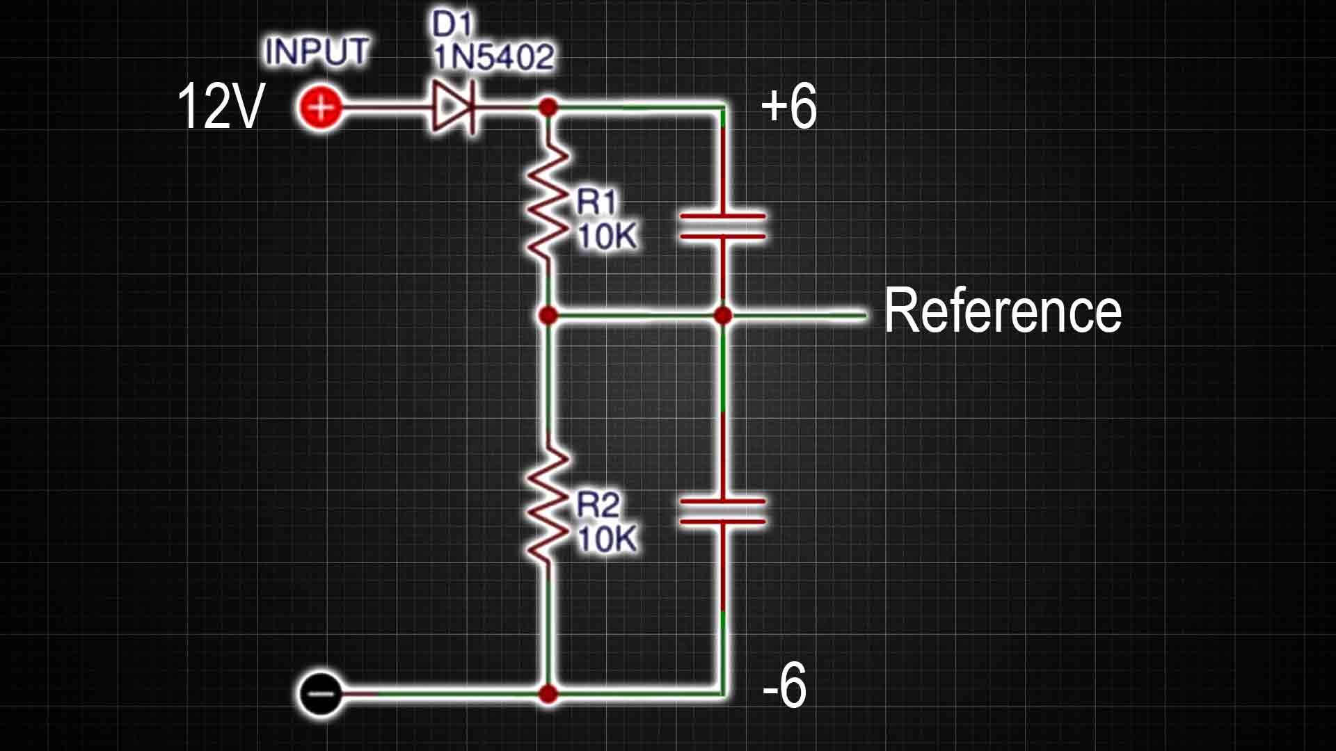
Ok so we need two resistors and two capacitors. Basically, if we add let’s say two 10K resistors in series like below, we will have a voltage divider in the middle point of this connection (Reference). If we take this middle point as a reference, then we would have a greater voltage on the top side and a lower voltage than the reference on the low side. I’ve made these connections on my breadboard. On the oscilloscope (in teh video), both references are in the middle and then we have a positive value with yellow and a negative value with green. Basically we get a two rail output, but is not that easy because the middle point would be a so-called virtual ground! If you add load to the output, the reference value changes and the values start to go up or down.
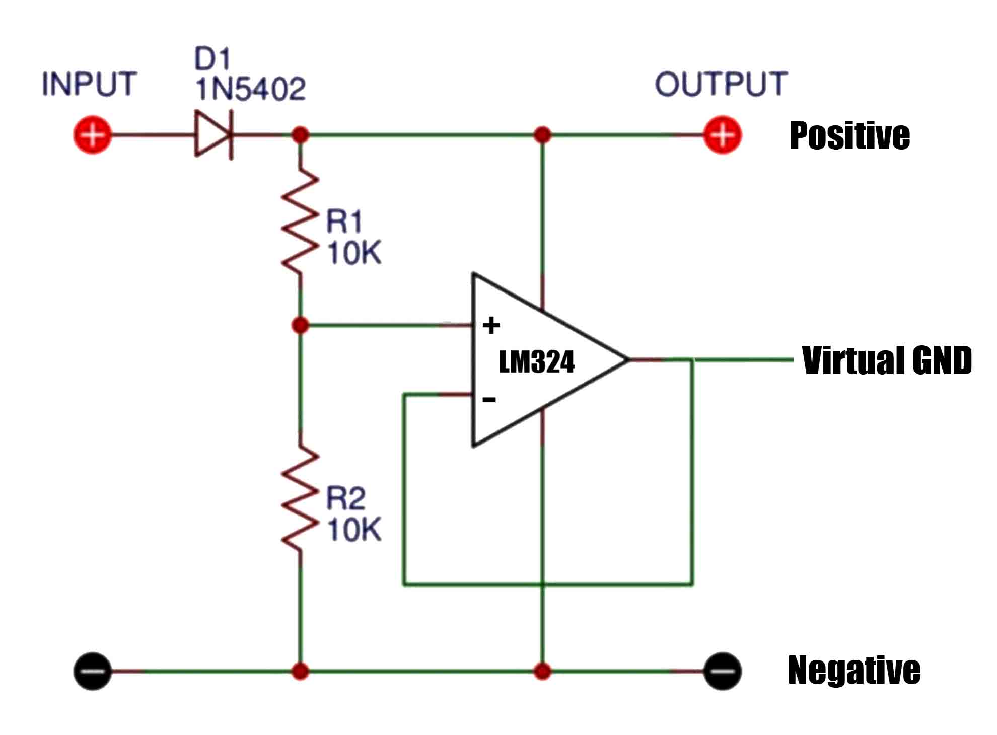
To solve that we add an OPAMP as a buffer. The main problem is that the previous circuit would be unstable. Is quite impossible to have two resistors with the exact same value. And if we add a load and if just a little bit more current is flowing through one side than the other, this would unbalance and we don’t want that. To solve this we add an operational amplifier on the middle point. The OPAMP will do everything possible to keep the voltage at the negative input to be the same as the one on the positive input. Like that it will work as a buffer so we have no current disturbance on the resistors and now we get a more decent virtual ground.
I’ve mounted this on my breadboard and test it out. As you can see in the video we get a decent two rail supply with plus 5.7V volts and negative 5.7V volts even if on the oscilloscope the value are a bit different. This time if I add a load, the output is not affected anymore as you can see, so we solved that problem. But obviously, in this case the current limit is given by the operational amplifier, so if the OPAMP could only deliver let’s say 50mA, that would be the maximum current the dual rail supply would have.
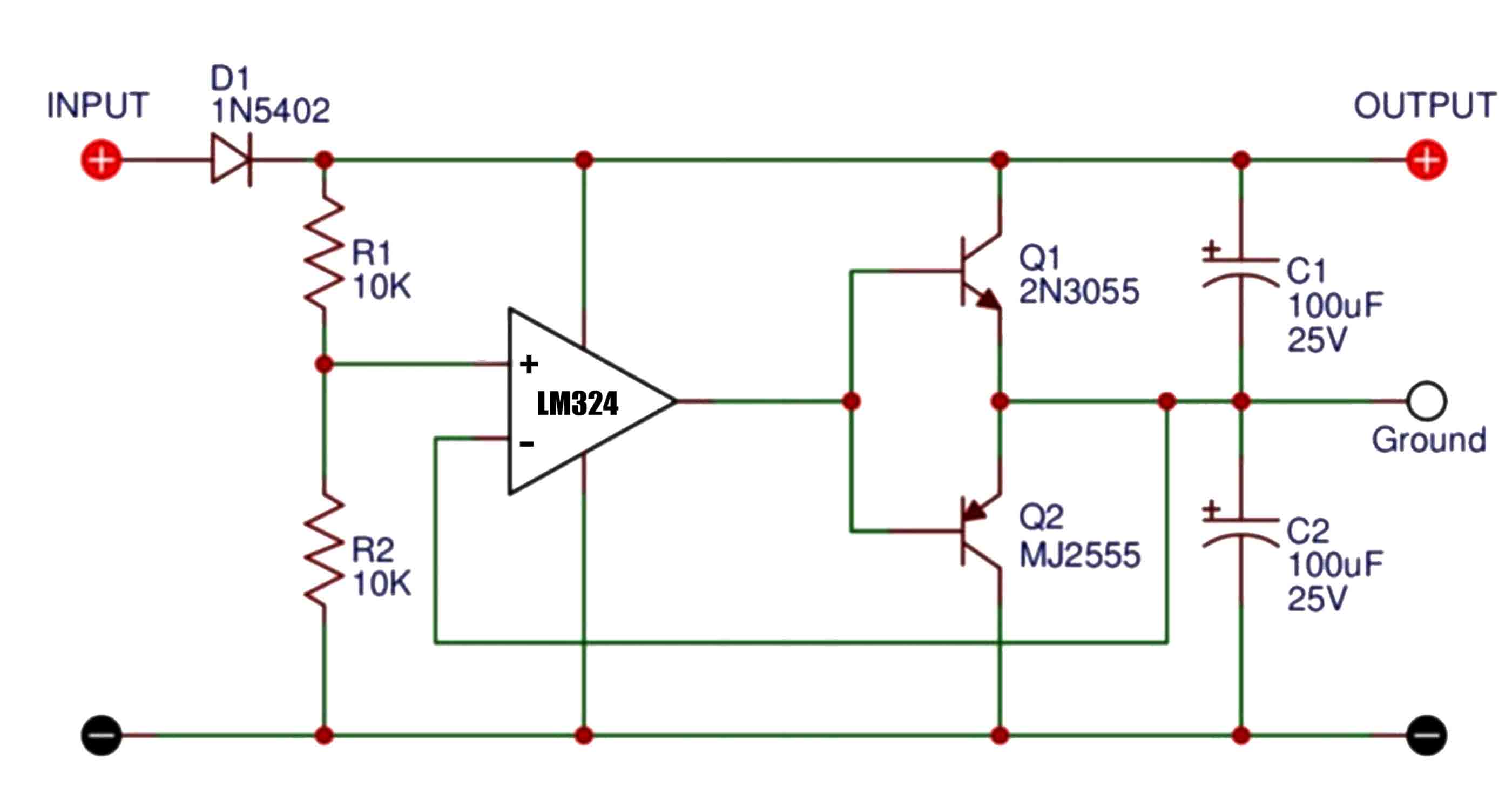
To make this even better we could try this approach below. We add two BJT transistors at the output and the buffer negative input is not connected at this point. We also add the capacitors at the output. Also add a diode at the input to protect the supply for reversed polarity. Like this, the current would be provided by the transistors and not the OPAMP, so the value would be higher this time, maybe something like 250mA or even more.
Ok but now let’s check the next solution. For this we need a boost converter but you could also do it with a buck converter. Anyway, as we all know, this is a switched mode kind of power supply. Basically it means that in order to regulate the output, it has a dedicated IC that switches on and off. So let’s say you apply 5V and the input, it will give let’s say 12V at the output. This circuit uses a coil together with a diode and a capacitor at the output to achieve that. To learn more about buck or boost converters, check my videos on those topics.
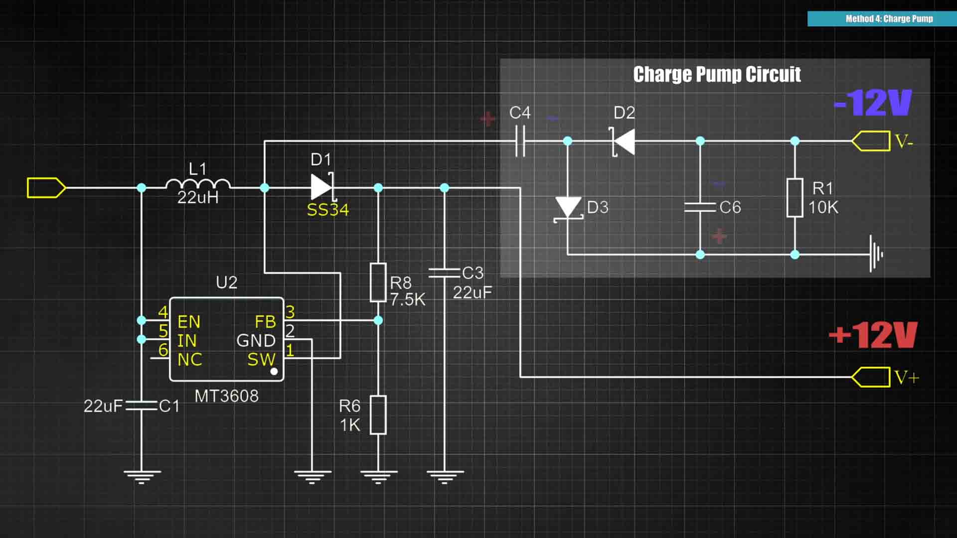
But anyway, if you add this other small circuit that is called a charge pump, between the coil and the diode, we can also get minus 12V at the same time. How you say? Well, let's see. Since this is a switched supply, that means we will have pules of voltage where the charge pump is connected. When the voltage pulse is HIGH, the first capacitor will charge up through the first diode towards ground. That will charge the capacitor with positive on one side and negative on the other. But when the pulse is on the LOW value, that point will simulate a ground potential. So basically, this second capacitor, since now the voltage is higher on the oposite side, it will charge up through the ther diode. But this time, it has the positive reference on the oposite side, which is the ground point, and a negative value on the top side, and that’s how we get those negative 12V. So basically this boost converter could now give 12V and negative 12V and the ground reference will be in the middle.
Now this kind of supply has the same problems as any other switched mode supply, and that is noise and oscillations. If we check the output on the oscilloscope and zoom in, we can see the typical pulses of a buck or boost converter. And on higher loads, the peaks are even bigger so for example for an audio amplifier this is not a good option since you don’t want that noise to pass to the audio. And the same problem would be for a precision sensor or an instrumentation amplifier which require very stable voltages. You can buy directly such modules from AliExpress for example and they could deliver an output from 50 up to maybe 500mA, which is not that much.
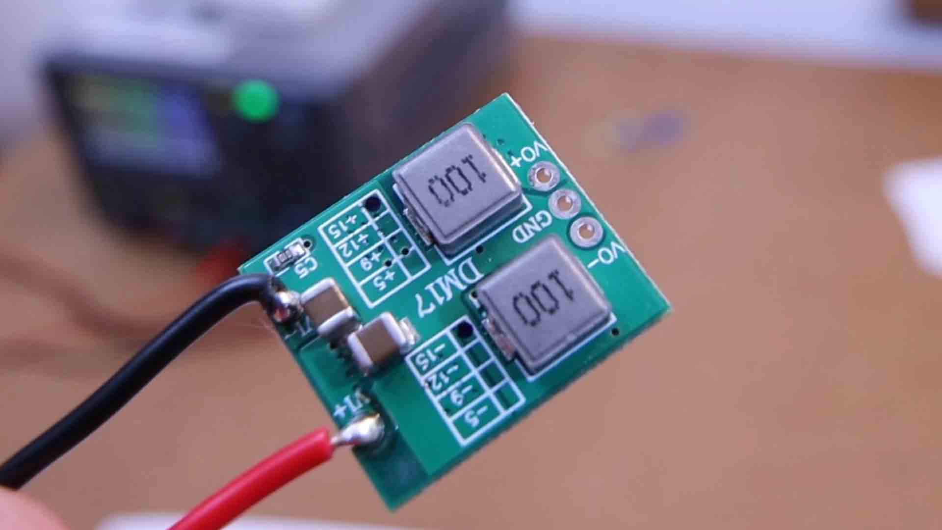
But this one here uses a different approach. Instead of using a single buck converter IC and then add the diodes and capacitors to create the negative rail, this one uses two buck converter ICs at the same time. One is the MP 14 84 and the other one, from what I found on the internet, is the TD 27 86. They can both deliver up to 3 amps of current so this time, the power output for both rails could be a lot higher than the previous example. As you can see it gives me plus and minus 15V.
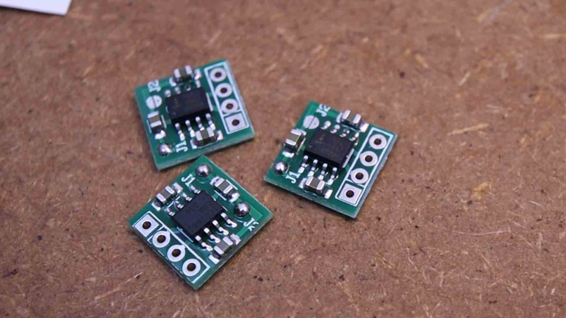
So by now, as you can see, the current output and noise problems are something common for a combination of a boost or buck converter together with a charge pump at the output. But if you don’t need too much current and you are looking for something smaller, you also have the ICL 76 62 which you could buy as a module or directly the IC and place it on your circuits. Look how small it is compared with the other modules. This can input from 4 up to 20V DC and it will output from -4 down to -20V. But the downside of this solution is the current output. It can only deliver 10mA of current so you can use it as a negative voltage reference but not as a powerful supply. And then you also have the ICL 76 60 and the TPS 60 403 which could go up to 60mA of current and is the same size. This IC only requires a small capacitor at the input and another one at the output and it requires no coils, diodes or any other component so consider this solution for any of your future projects that must be very small.
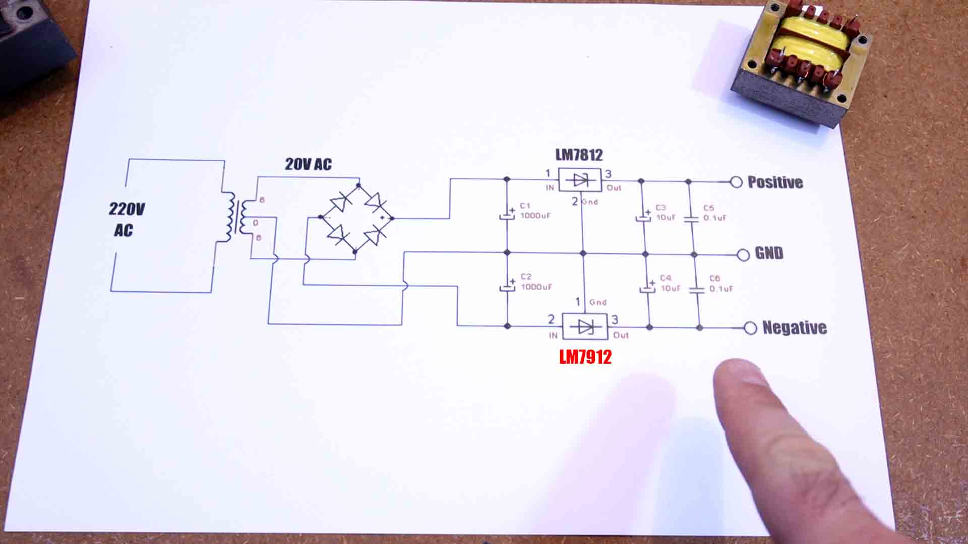
Ok, but now let’s get serious. How about when you need a steady and powerful negative rail supply? You won’t use switched converters or these tiny ICs that could only deliver a few mA of current. To get a decent power double rail supply we use a so-called center tapped transformer. This kind of transformer basically splits the secondary coil in half and we get the middle point as a ground reference and we will have positive on one side and negative on the other side. When the magnetic flux is oscillating inside such a transformer, the current will be induced on one side from ground towards one of the outputs and on the other side from the output towards ground, that’s how we can get both positive and negative voltages. Now the amount of windings on both sides must be the same if you want to get the same voltage values on each side. But to make sure we have the same voltage and also get rid of the noise, we add a filter and a linear regulator at the output. So the schematic would be something like this. We have the mains voltage of let’s say 220V AC and this would be its shape on the oscilloscope. Then we add the center tapped transformer and it will output plus and minus, let's say 20V and the shape would be the same as before but with a lower voltage. Then we have a full bridge rectifier and basically get half value on each rail. We would have the positive half of the wave on one side and the negative half wave on the other side. Then we add a filter using capacitors and we get a steady DC voltage. Then we add a linear regulator to let’s say 12V and minus 12V. That’s how we get a steady and decent power dual rail supply. Have in mind that the used LDO for the negative side must be one that accepts negative voltages such as the LM 79 12, otherwise it won’t work. So this is a more powerful way to get a dual rail supply but as disadvantage is that this time we use transformers which are very big, heavy and also work with mains supply so be very careful because they are dangerous.
So guys, these were some solutions to get a double rail power supply for your projects or to supply an audio amplifier, sensors, displays and much more. If my videos help you, consider supporting my work on my PATREON or a donation on my PayPal. Thanks again and see you later guys.


